

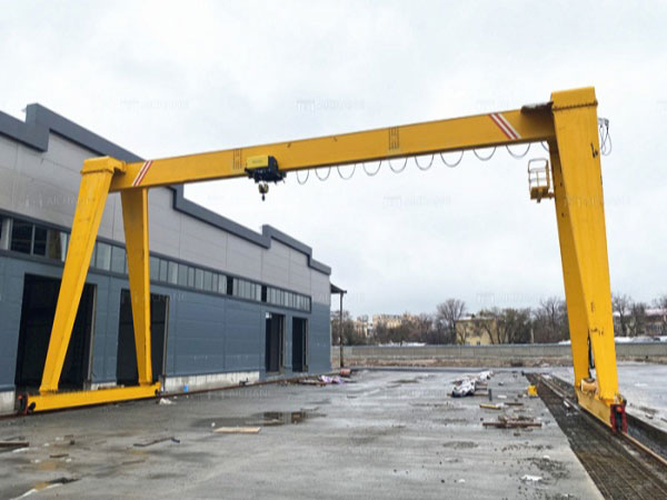

Description
Warning: mysqli_query(): (HY000/1194): Table 'wp_options' is marked as crashed and should be repaired in /www/wwwroot/excelcrane.com/wp-includes/class-wpdb.php on line 2349
Warning: mysqli_query(): (HY000/1194): Table 'wp_options' is marked as crashed and should be repaired in /www/wwwroot/excelcrane.com/wp-includes/class-wpdb.php on line 2349
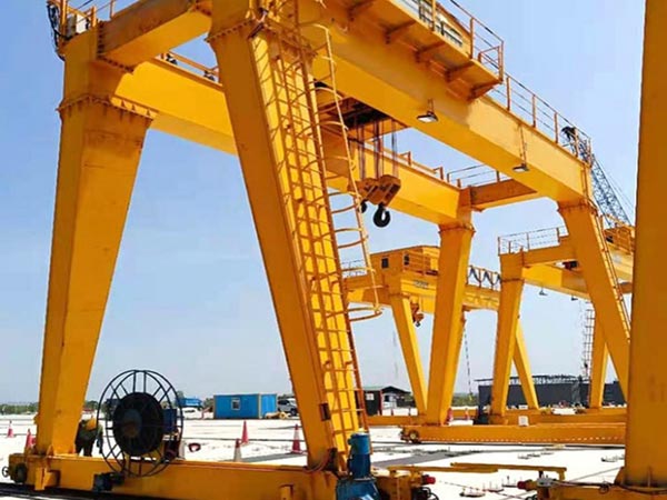
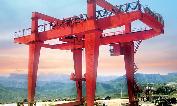
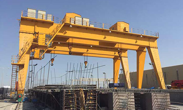
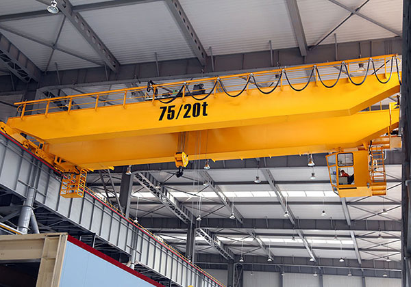
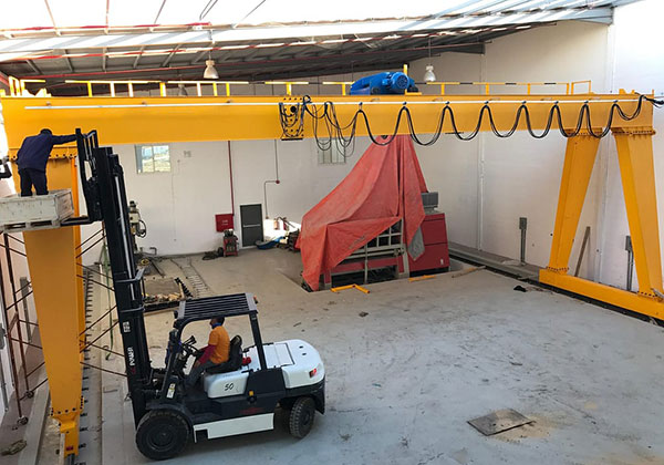
1. The crane adopts a single-beam design, simple structure and light weight, suitable for material handling in small and medium-sized factories or open sites. Supported by legs on both sides, it forms a door-shaped structure that can move along the horizontal plane on the track to adapt to different working areas.
2. 5 ton single girder gantry crane is a kind of lifting equipment widely used in industry and construction. It is composed of a single main beam, which can lift and move materials within a certain range. It is usually equipped with an electric hoist as the lifting mechanism, and the hoist moves along the main beam to complete the lifting and lateral movement of materials.
3. The maximum lifting capacity of this crane is 5 tons, which is suitable for handling medium-weight materials. The span can be customized according to user needs, usually in the range of 10-30 meters. The lifting height is generally between 6-12 meters and can be adjusted according to specific needs. It is generally A3 or A4 class and is suitable for medium-frequency working environments.
4. This crane can be operated by a button control box hung on the equipment, which is simple and convenient. It can also be equipped with an optional wireless remote control system, so that the operator can remotely control it from a safer location.
5 ton single girder gantry crane is widely used in various industrial and construction occasions due to its compact structure, easy operation and convenient maintenance. It is an ideal choice for small and medium-sized material handling.
Components of 5 ton mobile gantry crane
1. Main girder
- The main beam usually adopts a box-shaped structure, which is welded from steel plates and has high rigidity and bending resistance. The design of the box beam helps to reduce the deadweight while providing sufficient strength to withstand the lifting weight and dynamic loads. In some light or small and medium span occasions, I-beam structures are also used. I-beam beams have good load-bearing capacity and are suitable for small gantry cranes.
- The main beam is usually made of high-strength low-alloy steel or high-quality carbon steel to ensure that the beam body can carry heavy objects while having high safety and durability. In order to adapt to various working environments, the surface of the main beam is usually painted or coated to prevent rust and increase service life.
- The main beam is the main load-bearing component of the crane. The design needs to take into account the rated lifting weight, span and load distribution of the crane under various working conditions. The lower edge of the main beam is usually provided with a guide rail, and the electric hoist or trolley can move along the guide rail to achieve lateral displacement of the hoisted object. The two ends of the main beam are connected to the legs through a connecting plate to form a frame of the portal structure. The design of the connection point ensures the stability and overall rigidity of the structure.
- During the manufacturing process of the main beam, automatic welding or manual welding technology is used to ensure the quality and strength of the weld and avoid welding defects. After manufacturing, the main beam needs to undergo strict calibration and testing, including dimensional inspection, non-destructive testing, etc., to ensure that it meets the design standards and usage requirements.

2. Lifting System
- In the lifting system: The electric hoist is the core component of the lifting system and is responsible for lifting and lowering materials. It usually includes components such as motors, reducers, drums, wire ropes, hooks, etc. The wire rope is used to connect the hook and the electric hoist, and the lifting and lowering of materials are achieved through the rotation of the drum. The wire rope must have high strength and wear resistance to ensure safety. The hook is connected to the electric hoist through the wire rope and is used to grab and fix materials. The hook is usually designed to be rotatable or have an anti-slip device to increase the flexibility and safety of operation.
- Its working principle is that the motor of the electric hoist drives the reducer through the transmission system, and the decelerated power is transmitted to the drum, causing the drum to rotate around the axis. The rotation of the drum causes the wire rope to wind up or loosen, which in turn drives the hook and the material it carries to rise and fall. The operator controls the start, stop and running speed of the electric hoist through a control system (such as a handle or remote control) to accurately adjust the lifting height of the material.
- The system is designed to lift 5 tons, which is suitable for medium-weight material handling needs. Usually the lifting speed of the electric hoist is between 5-15 m/min, which can be adjusted according to the specific model and needs. The lifting system is equipped with limit switches and brakes to prevent overwinding and misoperation, ensuring the safety of lifting.
- The lifting system is usually equipped with a ground control handle, which directly controls the lifting and lowering of the electric hoist through buttons. In certain cases, a wireless remote control system can also be selected, so that the operator can control the lifting and lowering of materials without approaching the crane, improving safety and convenience of operation.

3. End Carriages
- The end beam is usually a box-shaped structure, welded with steel plates. The box-shaped structure provides high rigidity and strength, and can effectively support the weight of the main beam and the lifting system. In some light applications, the end beam may also adopt an I-beam or H-beam structure. This design can reduce the deadweight while ensuring strength.
- The end beam is an important component connecting the main beam and the traveling mechanism, which plays the role of supporting and stabilizing the main beam. The end beam evenly distributes the load of the main beam to the traveling wheels of the crane. The end beam connects the traveling mechanism of the crane, including the wheel set and the drive device, so that the crane can move horizontally along the track.
- The wheel set is installed on the end beam, usually consisting of two sets of driving wheels and driven wheels. The wheel set can be a cast steel wheel or an alloy steel wheel with high strength and wear resistance to ensure smooth operation. The end beam on one side is usually equipped with a drive device, including an electric motor and a reducer, which drives the wheel through a chain or gear transmission system to move the crane along the track.
- The end beam is usually made of high-quality low-carbon steel or alloy steel to ensure that it has sufficient strength and toughness to withstand various loads during equipment operation. High-quality welding technology is used in the manufacturing process of the end beam, and the welds need to undergo strict quality inspection to ensure that they are free of defects such as cracks and pores.
- The end beam design of the 5-ton single-beam gantry crane plays a vital role in ensuring the stability, durability and safety of the equipment. Reasonable design and careful maintenance can ensure that the crane operates smoothly and efficiently in various environments.
4. Crane traveling mechanism
The trolley running mechanism of the 5-ton single-beam gantry crane is the key system for the crane to achieve lateral movement, and is responsible for driving the entire crane to run smoothly along the track. This mechanism ensures that the crane can perform material handling operations at different locations within the work site. The following is a detailed introduction to the trolley running mechanism:
- Its driving device is usually composed of an electric motor, a reducer, a brake and a driving wheel, and is the core component of the trolley running mechanism. The wheel group includes a driving wheel and a driven wheel, which are installed on the end beam. The trolley operation of the crane is realized by the rolling of the wheels on the track. The power of the motor is transmitted to the wheels through a coupling, gear or chain to drive the wheel group to move along the track.
- The working principle of the crane is that the motor converts high-speed and low-torque power into low-speed and high-torque power through a reducer and transmits it to the driving wheel. The friction between the driving wheel and the track causes the wheel to roll on the track, driving the entire crane to move along the track to achieve lateral displacement of the trolley. The brake is activated when the operation stops or in an emergency to ensure that the trolley stops quickly and avoids exceeding the operating range due to inertia.
- The trolley running mechanism of this crane is equipped with a motor with sufficient power and an efficient reducer, which can stably drive the 5-ton crane to run on the track. The wheel group is reasonably designed, made of high-strength materials, and is precisely processed and assembled to ensure that the wheels roll smoothly on the track and reduce vibration and noise. The operator can accurately control the running speed and stop position of the trolley through the control panel or remote control to meet the needs of different working occasions.
- The wheels, bearings and other key components are made of high-strength steel, with excellent wear resistance and durability, and can withstand long-term high-load operation. The wheels and gears are precisely processed to ensure high-precision size and shape, thereby ensuring the stability and reliability of the trolley operation.

5. Trolley traveling mechanism
- The motor of the trolley running mechanism transmits power to the driving wheel through the reducer, driving the trolley to move along the track of the main beam. The walking wheel rolls on the track at the lower edge of the main beam, allowing the trolley to move laterally on the main beam, thereby adjusting the position of the material. Through a precise control system, the smooth and synchronous operation of the trolley is ensured to avoid offset or jamming.
- The trolley running mechanism can achieve precise lateral movement on the main beam, which is convenient for operators to position the hoisted materials to the specified position. The trolley’s walking wheel group is precisely machined to ensure its smooth rolling on the track and reduce vibration and noise during operation. The drive device uses a high-efficiency reducer and transmission mechanism to ensure that the trolley can still maintain a stable running speed under load.
- The trolley frame and walking wheel are made of high-quality steel with high strength and wear resistance, and can withstand high loads and frequent operation. The walking wheel and drive components are precisely machined to ensure that they are well matched with the main beam track, reducing wear and running resistance.
- The wear of the walking wheel needs to be checked regularly, and lubricated or replaced when necessary to ensure the smooth operation of the trolley. Regularly lubricate the trolley’s drive device and travel wheel bearings to reduce friction and extend the life of the equipment. Ensure that the electrical system of the electric hoist and drive motor operates normally, and regularly check electrical components such as cables and control systems.
6. Crane wheel
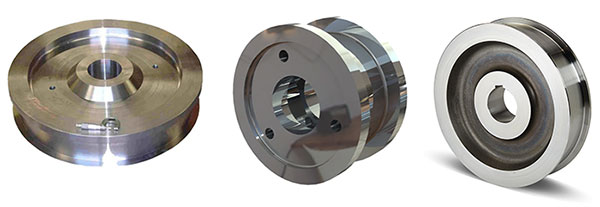
Wheels are usually designed with raised rims to prevent derailment when the wheels are running on the track. The height and angle of the rims are optimized to balance the anti-derailment ability and running resistance. The wheels are well matched with the bearings, and the selection and installation of the bearings play an important role in the smooth running of the wheels. Rolling bearings are usually used to reduce friction and improve running efficiency. In order to increase the wear resistance and corrosion resistance of the wheels, the wheel surface may be specially treated, such as quenching or spraying wear-resistant materials.
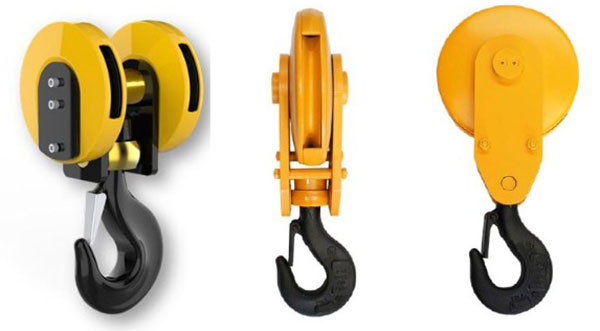
7. Crane hook
- Types of hooks: Single hooks are the most common type of hooks, consisting of one hook body, and are suitable for most common lifting operations. Double hooks consist of two symmetrical hook bodies and are usually used in situations where balanced force is required, such as the lifting of long materials. Hooks with swivel functions have swivel bearings that allow the hook to rotate freely during lifting to avoid twisting of the wire rope or chain.
- Materials and manufacturing: Hooks are usually made of high-strength alloy steel and are processed by forging processes to improve their strength, toughness and wear resistance to ensure that they will not break or deform under high loads. The hooks undergo heat treatment processes such as quenching and tempering to improve their surface hardness and wear resistance, while ensuring the toughness of their internal structure to prevent brittle fracture. The key parts of the hook, such as the hook mouth, hook body and hook shaft, are precision machined to ensure dimensional accuracy and surface quality to ensure good coordination with other lifting components.
- Structural design: The main part of the hook is designed to be streamlined to facilitate load bearing and load distribution while reducing damage to the hoisted object. The design of the hook mouth must meet safety standards and is usually slightly smaller than the inner diameter of the hook body to prevent the weight from slipping during lifting. Many hooks are equipped with a safety clip (also called a safety lock plate). When the weight is hung on the hook, the clip will automatically close to prevent the weight from accidentally falling off.
- Working principle: The hook is connected to the lifting system through a wire rope, chain or other connector, transferring the load to other parts of the crane and directly acting on the lifted material. During the lifting process, the hook evenly distributes the weight of the weight to the entire lifting system through the hook body to ensure stability and safety during the lifting process. Some hooks are designed with a rotating mechanism that allows the hook to rotate freely with the rotation of the weight during the lifting process to avoid entanglement and twisting of the wire rope or chain.
8. Motor
- The motor of a 5-ton single-beam gantry crane is a key component that provides power for the various moving mechanisms of the crane. It is mainly used to drive the crane’s trolley, car and lifting system. The performance of the motor directly affects the working efficiency and safety of the crane.
- The motor converts electrical energy into mechanical energy through the principle of electromagnetic induction to drive the various parts of the crane. The three-phase AC current generates a rotating magnetic field through the stator winding, which in turn drives the rotor to rotate and output mechanical energy. The motor transmits power to the trolley, car or lifting mechanism through a coupling or gearbox to drive these mechanisms to move along the track or lift heavy objects. For lifting motors, brakes are usually integrated. When the motor is powered off or stops running, the brake will automatically act to prevent the load from sliding down due to gravity.
- The motor design adopts high-efficiency energy-saving technology, which can reduce energy consumption and improve work efficiency while ensuring strong power output. The motor usually has good starting performance and can achieve smooth starting under heavy load conditions to avoid impact and damage to the mechanical structure. Using high-quality materials and advanced manufacturing processes, the motor can withstand high-load operation for a long time and has excellent durability and reliability.

9. Sound and light alarm system & limit switch
- The sound and light alarm system warns the operator and surrounding personnel that the crane is in operation or has potential dangers by emitting sound and flashing light signals to avoid accidents. When the crane fails or has abnormal conditions, the sound and light alarm system will automatically activate to remind the operator to take timely measures to prevent the accident from expanding. At the beginning of the key steps of the lifting operation (such as lifting, lowering, moving, etc.), the sound and light alarm system will send a signal to remind the operator and on-site personnel to pay attention to ensure safe operation.
- When the crane is started or performs key operations, the control system will automatically activate the sound and light alarm and send out corresponding sound and light signals. In the event of abnormal conditions (such as overload, limit switch triggering, etc.), the controller will immediately trigger the alarm system to remind the operator to stop the operation and check the problem. The sound and light alarm system can be operated by manual control or automatic control, depending on the design and application requirements of the crane.
- The limit switch is used to limit the range of motion of the crane to prevent the trolley, car or lifting mechanism from exceeding the safe operating range, thereby avoiding equipment damage or safety accidents. When the moving parts of the crane (such as the trolley, car or hook) reach the set limit position, the limit switch will automatically cut off the power supply or send a signal to stop the movement to prevent continued operation from causing accidents. The limit switch effectively prevents the mechanical structure of the crane from overloading or impacting, thereby protecting the safe operation of the crane.
- When the trolley, crane or lifting mechanism moves to the preset limit position, the moving parts will trigger the limit switch trigger, and the limit switch will immediately act to cut off the power supply of the drive motor or send a stop signal. The action of the limit switch can be instantaneous or delayed by the control system to ensure the safe stop of the equipment.

10. Safety Devices
The safety device of a 5-ton single-beam gantry crane is a key component to ensure the safe operation of the equipment and prevent accidents. The following are common safety devices and their functions:
- Overload protection device: prevents the crane from running under overload conditions, protecting the safety of equipment and personnel. Monitors the load conditions, and automatically alarms and limits the operation of the equipment when the load exceeds the set value.
- The braking system ensures that the crane can reliably hold the load when it stops, preventing the load from sliding due to power outages or operating errors. When the motor stops, the brake automatically applies braking force to ensure that the load is stable.
- Safety locking device: prevents the crane from accidentally starting during maintenance or overhaul. When performing maintenance or overhaul, the operator can enable the locking device to prevent the equipment from starting.
- Slow start and slow stop device: reduce the impact on the mechanical structure when the equipment starts and stops, and protect the equipment. Adjust the starting and stopping speed of the motor to make it a smooth transition and reduce vibration and impact.
- Anti-collision system: prevents the crane from colliding with surrounding objects during operation. Detects the position of surrounding obstacles, issues an alarm when approaching obstacles, and automatically stops the equipment.
- Limit alarm device: When the equipment approaches the limit position, an alarm is issued to remind the operator. When the equipment approaches the preset limit position, the limit sensor is triggered to sound an alarm, reminding the operator to make timely adjustments.
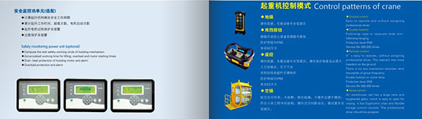
11. Control Mode
- Manual control: The operator controls the movement of the crane by manually operating the controller (such as handles, switches, etc.). This method is simple and direct, and is suitable for smaller cranes or operating occasions with low requirements.
- Electric control button operation: The operation through the electric control button panel can realize the start, stop, adjustment and other functions of the moving parts of the crane. The operation is intuitive and can centrally control the various functions of the crane, which is suitable for small and medium-sized cranes.
- Wireless remote control: Use a wireless remote control for operation, and control various movements and functions of the crane through wireless signals. The operation is flexible, and the operator can stay away from the crane, which is suitable for larger working spaces.
- Wired remote control: The crane is controlled by a wired remote control (handheld controller), and the cable transmits the signal to the crane’s control system. The operation is stable, avoiding wireless interference, and is suitable for occasions requiring high reliability.
Different control methods can be selected according to actual needs and working environment to improve the operating efficiency and safety of the crane.
12. Sketch

Application of 5 ton mobile gantry crane
5-ton single-beam gantry crane is suitable for various applications due to its simple structure, economical and practical, flexible operation and other characteristics. The following are the main applications and functions of 5-ton single-beam gantry crane:
- Warehouse: used for loading and unloading and handling of goods in the warehouse, such as between shelves and stacking areas in the warehouse. Transfer materials inside the warehouse, cooperate with forklifts, transporters and other equipment to improve work efficiency. Lift goods from the ground to a specified height for storage or loading and unloading. Move goods horizontally to different storage locations or work areas in the warehouse.
- Production workshop: Handle raw materials, semi-finished products or finished products in the production workshop, such as moving raw materials to the production line or moving finished products to the shipping area. Used for the installation, adjustment and maintenance of production equipment.
- Construction site: Used to carry construction materials such as steel, concrete prefabricated parts, etc. on the construction site. Lift construction equipment, tools, etc. to the construction height. Lift construction materials to a high place for construction or installation. Move materials and equipment on the construction site to improve construction efficiency.
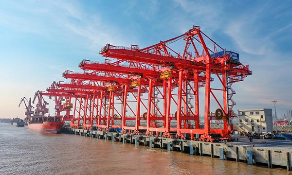
- Dock: It is used to load and unload cargo from ships at the dock, transfer cargo from ships to docks or load cargo from docks to ships. It is used for loading and unloading containers and transshipment. It lifts containers or bulk cargo from the ground to transport vehicles, or unloads them from transport vehicles to the ground.
- Repair and overhaul: It is used to repair and overhaul large equipment such as motors, transformers, etc. It performs overhaul and maintenance of facilities in industrial facilities or buildings. It lifts the equipment and tools required for repair or overhaul to the working position.
The main application occasions of 5-ton single-beam gantry cranes include warehouses, production workshops, construction sites, docks, assembly workshops, repair and overhaul, and logistics centers. Its functions include lifting and horizontal movement of cargo, and it is suitable for various occasions where materials need to be handled and processed. Its advantages are economical and practical, flexible operation, and the ability to improve work efficiency and optimize the operation process.

Advantages of 5 ton mobile gantry crane
5-ton single-beam gantry crane is a common lifting equipment widely used in factories, warehouses, docks and construction sites. It has many advantages and is suitable for various lifting operations. The following are the main advantages of 5-ton single-beam gantry crane:
- Simple structure and low cost: The single-beam design has a simple structure and relatively low manufacturing and maintenance costs. This makes the 5-ton single-beam gantry crane a cost-effective choice for projects with limited budgets.
- Simple structure and low cost: The single-beam design has a simple structure and relatively low manufacturing and maintenance costs. This makes the 5-ton single-beam gantry crane a cost-effective choice for projects with limited budgets.
- Flexible and convenient operation: It can be operated by various control methods (such as manual, electric control, wireless remote control, etc.), making the operation flexible and convenient. Suitable for working environments that require frequent adjustments and operations.
- Convenient installation and disassembly: The structure of the single-beam gantry crane is relatively simple, and installation and disassembly are relatively easy, which shortens the installation time and cost. Suitable for places where equipment needs to be moved or reconfigured frequently.
- Strong load-bearing capacity: Although it is a single-beam design, the 5-ton single-beam gantry crane can still provide sufficient load-bearing capacity to meet the lifting needs of small and medium-sized loads.
- Easy maintenance and upkeep: Due to its simple structure, maintenance and upkeep are relatively easy, and component replacement and overhaul are also relatively convenient, reducing equipment downtime.
The 5-ton single-beam gantry crane has become a commonly used lifting equipment in many industries due to its simple structure, low cost, and easy operation. According to actual needs, different control methods and configurations can be selected to give full play to its advantages.
Main technical data

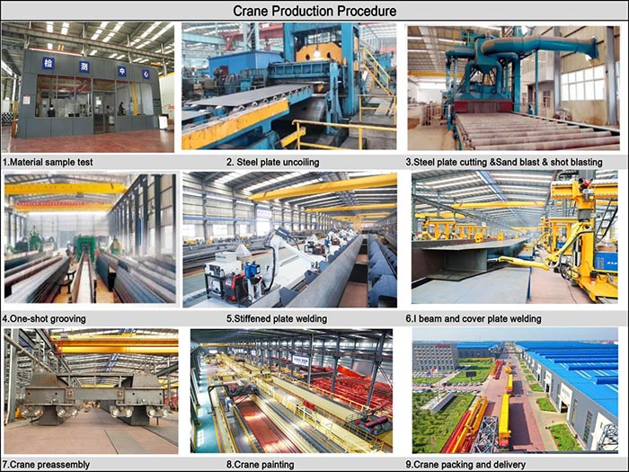
Crane production procedure
The production of a 5-ton single-girder gantry crane involves multiple steps, from design to final assembly and testing. The following are the main production steps of a 5-ton single-girder gantry crane:
- Design and Engineering: Communicate with customers to understand the needs and application scenarios, and determine the basic specifications and functional requirements of the crane. Carry out detailed design according to the needs, and draw structural drawings, layout drawings and component drawings. Including the design of the main beam, end beam, lifting system, trolley running mechanism, trolley running mechanism, etc. Select suitable materials such as steel, bearings, motors, etc. to ensure that the load-bearing capacity and durability requirements are met.
- Material procurement: Select reliable suppliers to purchase the required raw materials and components. Carry out quality inspection on the incoming materials to ensure that they meet the design standards and safety requirements. Prepare qualified materials, classify and store them for subsequent processing.
- Parts processing: Cut steel and other materials according to the requirements of the design drawings to prepare the required parts. Weld the cut steel to form the main beam, end beam and other main structural parts. Perform fine processing on the welded parts, such as turning, milling, drilling, etc., to ensure the size and accuracy of the parts. Heat treatment of important structural parts to improve the strength and hardness of the material.
- Component assembly: Assemble the main structural parts such as the main beam and end beam to ensure that the connection is firm and meets the design requirements. Install the motor, reducer, lifting mechanism, etc. to ensure the normal operation of the lifting system. Install the wheels, reducer, etc. of the trolley running mechanism to ensure the smooth operation of the trolley. Install the wheels, motors, etc. of the trolley running mechanism to ensure the normal operation of the trolley. Arrange the electrical system, including cables, control boxes, limit switches, etc., to ensure the normal operation of the electrical control system.
- Debugging and testing: Check the installation of each component of the crane to ensure that there is no looseness or improper installation. Perform functional tests on the crane, including lifting, moving, braking, etc., to ensure the normal operation of each function. Test the working conditions of safety devices, such as limit switches, overload protection devices, sound and light alarm systems, etc., to ensure their effectiveness. Perform load tests during the test phase to confirm the operating performance and stability of the crane under rated load.
- Inspection and acceptance: Conduct comprehensive quality inspections, including material quality, processing accuracy, assembly quality, etc., to ensure compliance with standards. Invite customers or third-party organizations to conduct acceptance tests to confirm that the performance indicators of the equipment meet the contract requirements. Prepare relevant technical documents, instruction manuals, safety operating procedures, etc. and deliver them to customers.
Global Market

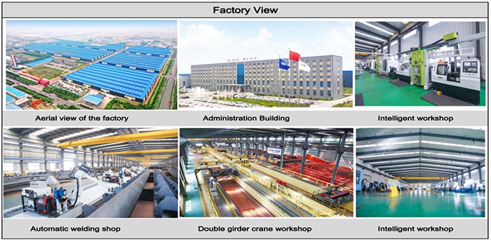
Workshop view
The company has installed an intelligent equipment management platform, and has installed 310 sets (sets) of handling and welding robots. After the completion of the plan, there will be more than 500 sets (sets), and the equipment networking rate will reach 95%. 32 welding lines have been put into use, 50 are planned to be installed, and the automation rate of the entire product line has reached.