

Description
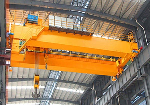
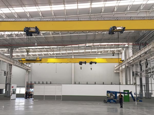
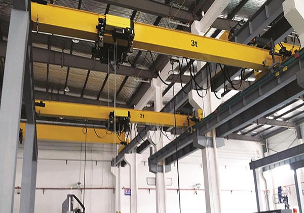
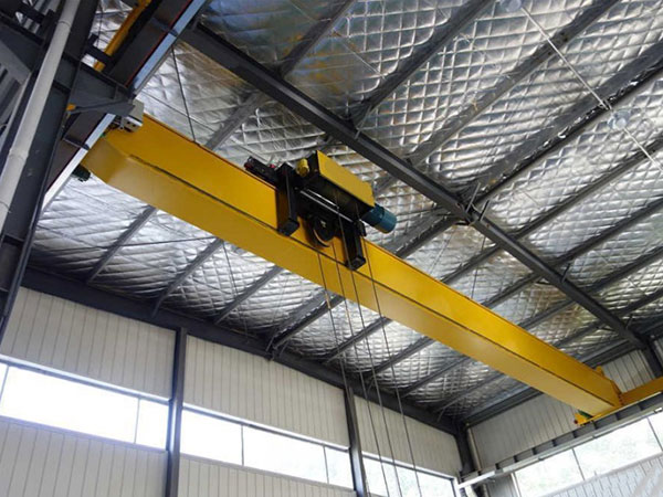
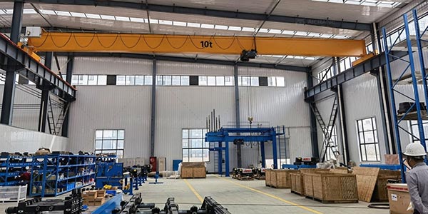
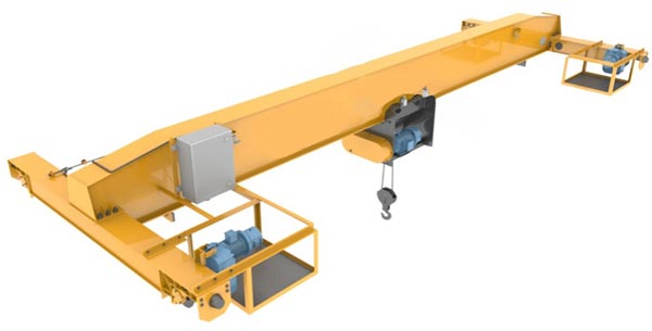
Single-beam overhead crane is a kind of lifting equipment commonly used in factories or warehouses. It consists of a horizontal main beam (single beam) and a trolley running on the main beam. It is usually used for lifting and handling operations of small and medium-sized loads.
The main beam is the main load-bearing part of the crane, supporting the entire structure of the crane, and is usually designed with a box beam or I-beam. The trolley runs along the track on the main beam and is equipped with an electric hoist or other lifting equipment to be responsible for vertical lifting and lowering.
The design of the main beam and trolley is optimized, so that the crane can efficiently move the cargo vertically and horizontally. The main beam structure is carefully designed and calculated to ensure the stability and safety of the crane when working. This crane can be equipped with different types of slings and accessories to meet different work needs. Equipped with a variety of safety devices, such as overload protection, limit switches, emergency brake systems, etc., to ensure safety during operation.
Single-beam bridge cranes generally require professional installation to ensure the precise docking of the main beam and the track system. Regular inspection and maintenance, including lubrication, inspection of electrical systems and structural parts, are required to keep the equipment running normally. Single-girder bridge cranes are ideal for many industrial sites due to their simple structure, stable performance and relatively low cost.
Components of motor-driven single beam overhead crane
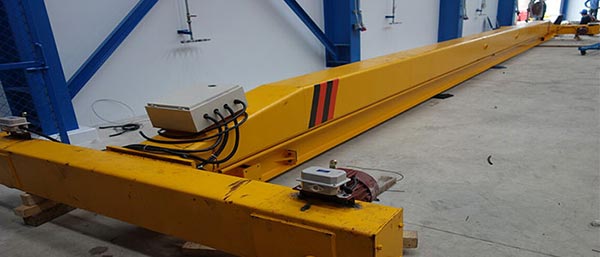
1. Main girder
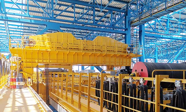
The main beam of a single-beam bridge crane usually adopts a box-shaped structure. This structure consists of upper and lower covers, vertical webs on both sides, and internal ribs, and has good bending and torsion resistance. The advantage of the box-shaped structure is that its closed frame can effectively disperse and carry forces from all sides, thereby improving the load capacity of the main beam.
In terms of material selection, high-quality steel is usually used for the main beam. The selection of steel needs to take into account its yield strength, toughness, and welding performance to ensure the safety and reliability of the main beam under heavy loads and complex working conditions.
The connection method between the main beam and the end beam directly affects the stability and service life of the crane. The common connection method is bolt connection, which is easy to install and maintain, and can also provide sufficient connection strength to ensure the firmness between the main beam and the end beam. The supporting structure of the main beam includes the trolley running mechanism and the wheel-rail system. These structures need to match the design parameters of the main beam to ensure that the crane has good stability and smoothness when working.
High-quality manufacturing process is the key to ensuring the quality of the main beam. In the manufacturing process of the main beam, welding is an important link. Appropriate welding materials and processes need to be used to avoid welding deformation and cracks and ensure the uniformity and firmness of the weld. In the design of the main beam, safety during use must be taken into consideration. Setting necessary safety protection devices, such as overload protection and limit switches, can improve the safety of crane use and reduce safety accidents caused by operating errors.
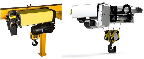
2. Lifting System
Drive device: The lifting mechanism of a single-beam bridge crane usually uses an electric motor as the drive device, mainly because the motor is simple to arrange, easy to install and relatively convenient to maintain.
Transmission device: This part includes a reducer, a coupling and a transmission shaft, etc., which are used to transmit the power of the motor to the winding system.
Winding system: The winding system includes a drum, a wire rope and a pulley block. It is the part of the lifting mechanism that is directly connected to the object being hoisted. Its function is to retract and release the wire rope through the rotation of the drum, thereby realizing the lifting and lowering of the hook.
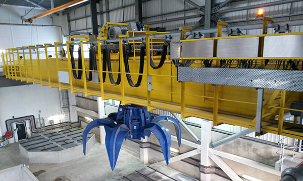
Pick-up device: The pick-up device is designed according to the type and shape of the material being hoisted, including various hooks and clamps to meet the lifting requirements of different items.
Safety protection device: The safety protection devices in the lifting system, such as brakes, overload limiters and rising limit position limiters, are important guarantees for ensuring the safe operation of the lifting operation.
3. End Carriages
The end beam plays a vital role in the single-beam bridge crane. The entire bridge of the crane is mainly composed of the main beam, the end beam and other accessories. The end beam is usually welded into a box shape with steel plates, and holes are bored on the box beam to install the wheel set. The main beam and the end beam are connected by connecting plates and bolted together to ensure the stability and firmness of the entire bridge.
The design of the end beam must be able to withstand various forces generated during the overall operation of the crane. The end beam not only needs to have sufficient strength and rigidity, but also has good bending and torsion resistance. This is because during the operation of the crane, the end beam has to withstand the gravity from the main beam, the tension of the lifting object, and the vibration and impact generated during walking.
The manufacturing process of the end beam also requires precise welding technology and reliable quality control measures to ensure the structural firmness and service life. During the manufacturing process, strict quality inspections of various components of the end beam, including the uniformity of the weld, the flatness of the connecting plate, and the firmness of the bolt connection, are all important links to ensure the performance of the end beam.
4. Crane traveling mechanism
As one of the core components of the crane, the design and technical performance of the trolley running mechanism are directly related to the operating efficiency and safety performance of the whole machine. Due to the complexity and versatility of the trolley running mechanism, understanding and applying its working principle and maintenance methods are essential to ensure the long-term stable operation of the crane.
- Motor: The motor is the power source of the trolley running mechanism. Usually, a high-torque, low-speed motor is used to ensure the stability and adjustability of the output power.
- Reducer: The function of the reducer is to increase the torque by reducing the speed of the high-speed rotation generated by the motor, thereby driving the running mechanism to work.
- Coupling and drive shaft: The coupling is used to connect the motor and the reducer, and the drive shaft is responsible for transmitting power to the wheel. These components require a high degree of processing accuracy and good assembly quality to prevent vibration and impact during movement.
- Angular bearing box and trolley wheel: The angular bearing box is firmly mounted on the end beam to support the wheel and bear the load and impact force from the wheel. The trolley wheel is the part that directly contacts the track and is responsible for the travel of the crane.
5. Trolley traverling mechanism
The trolley operating mechanism of small and medium-sized cranes usually adopts a centralized drive form, that is, a motor drives the wheels on both sides through a transmission device. Large cranes mostly adopt a separate drive form, that is, multiple motors independently drive different wheel groups to improve efficiency and reliability.
The trolley operating mechanism must be equipped with brakes to ensure safe parking within the allowable braking range after power failure. At the same time, terminal travel limiters and buffers are installed at both ends of the trolley travel to ensure that the trolley can stop safely when it reaches the terminal to prevent collision accidents.
The trolley operating mechanism of a single-beam bridge crane is not only highly complex in technology, but also extremely important in terms of operational safety and application effect. Understanding its structure and working principle is crucial to the design, application and maintenance of cranes. In future development, technological innovation and intelligent application will be the key direction to improve the performance of the trolley operating mechanism.
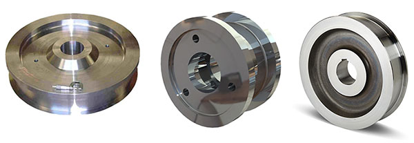
6. Crane wheel
The wheels of a single-beam bridge crane are key components in the crane’s mobile mechanism. They are mainly responsible for carrying the weight of the crane and the load of the hoisting weight, and transmitting these forces to the track to drive the crane or trolley to move forward, backward, left and right. The wheels of the crane not only affect the stability and safe operation of the equipment, but also require special attention when selecting materials and forms.
The wheels commonly used for single-beam cranes are mainly in the form of track-based walking wheels and suspended wheels. The materials of crane wheels are usually forged parts and ductile iron parts. Forgings often use 42CrMo alloy steel, while single-beam cranes mostly use 45 steel forged wheels. Forgings have a large load-bearing capacity and are suitable for environments with more severe working conditions.
The wheel group is mainly used in the crane to carry the weight of the equipment and the hoisting weight. The wheels are driven to rotate through transmission devices such as motors and reducers, thereby driving the crane or trolley to complete longitudinal and lateral movement. Through the mechanical action of forging, the forged wheel optimizes the organizational properties of the metal blank, eliminates organizational defects, and has better overall performance than cast wheels of the same material.
Regular inspection and maintenance of the wheels is essential, including assessment of wheel wear and inspection of the wheel rim. Damaged or excessively worn wheels should be replaced in a timely manner to ensure safe operation of the crane.
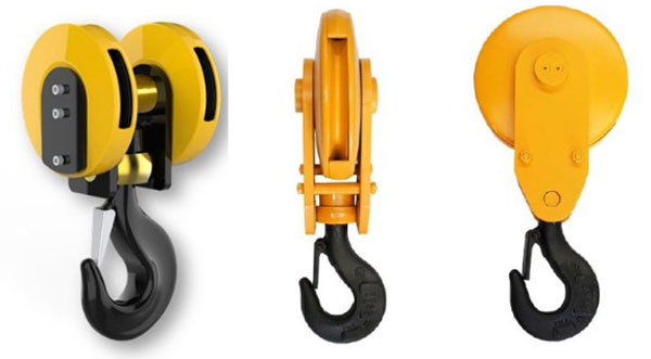
7. Crane hook
Hooks can be divided into many types. According to their shapes and uses, the most common ones are eye hooks, straight rod hooks, etc. Eye hooks are widely used in various lifting equipment because of their simple structure and easy use. The material of the hook is usually made of high-strength steel, such as alloy steel, to ensure that it is not easy to break or deform when bearing heavy loads.
The hook is mainly used in the crane to directly grab and carry goods, and transmit the force of the lifting mechanism to the goods through the wire rope and pulley block to achieve lifting or lowering operations. In order to ensure the safety of operation, the load limit and safety factor must be considered when designing the hook. The maximum lifting weight is usually marked on the hook to prevent overloading.
It is essential to inspect and maintain the hook regularly, including checking the surface cracks of the hook and testing the flexibility of the rotating part. Replace damaged or over-worn hooks in time to ensure the safe operation of the crane. Once the hook is cracked or permanently deformed, it should be scrapped immediately and must not be welded for repair.
8. Motor
The choice of motor has an important influence on the performance of single-girder bridge cranes. For example, for LD-type electric single-girder cranes, their operating mechanisms are usually driven separately, and braking is done by conical brake motors. This type of motor can provide stable power output and braking effect during the lifting process. In terms of lifting, cranes are often used in conjunction with electric hoists in the form of CDI, MDI, etc., and their lifting speed and running speed can be adjusted according to actual needs.

9. Sound and light alarm system & limit switch
Sound and light alarm system: The sound and light alarm system usually consists of an alarm, a control unit and a sensor. The alarm includes two parts: sound alarm and light alarm. The control unit is responsible for receiving signals from various sensors and processing these signals. The sensor is used to detect the status of the crane and the surrounding environment. When the crane is overloaded, the motor is overheated, the brake fails, the height limit and other abnormal conditions occur, the sound and light alarm system will start immediately, and the alarm will be issued to remind the operator to take emergency measures.
Limit switch: The limit switch mainly includes lifting height limiter, operation limiter, etc. These switches monitor the position of each component of the crane through physical connection or induction, and once the preset limit position is reached, the corresponding power source will be automatically cut off. For example, the lifting height limiter is used to prevent the hook from exceeding the set maximum height, to avoid the winch being too tight or hitting the top structure; the operation limiter limits the travel range of the crane on the track to prevent derailment or hitting the end structure.

10. Safety Devices
Overload limiter: detects whether the load of the crane exceeds the rated lifting capacity. If it exceeds, the system will sound an alarm and stop the lifting operation to prevent equipment damage or accidents caused by overload.
Buffer: installed at the end of the travel of the trolley or car to prevent violent collision of the running parts when reaching the limit position.
Windproof device: used for outdoor cranes to prevent the crane from being blown in strong wind environment. Including track clamps, anchoring devices, etc.
Emergency braking system: in an emergency, the power supply can be quickly cut off and the crane can be stopped in a short time to prevent accidents.
Rope breaking protection device: when the lifting wire rope breaks, it can automatically hold the lifting mechanism to prevent the hanging objects from falling.
Anti-collision device: used to prevent two cranes or lifting trolleys from colliding with each other when running on the same track, usually by installing proximity switches or radar sensors.
Automatic alarm system: when the crane fails or is improperly operated, it will automatically sound and light alarms to remind the operator to deal with it in time.
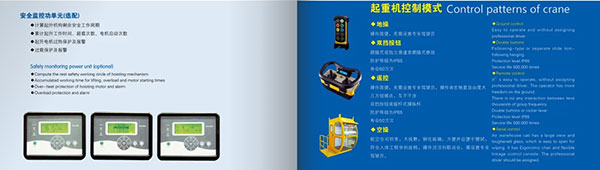
11. Control Mode
Flashlight control (hanging control panel): The operator directly controls the various movements of the crane through the flashlight (also known as the button operation box) hanging under the crane. The control panel is connected to the control system through a cable.
Wireless remote control: The operator controls the movement of the crane remotely through a wireless remote control. The remote control communicates with the crane control system through radio signals.
Cab control (operating room control): The crane is equipped with an operating room (cab), and the operator controls the crane through a joystick or button in the cab. This method provides a more comfortable and safe operating environment, especially for long-term or complex operations.
PLC control: Using a programmable logic controller (PLC) to automatically control the various movements of the crane can achieve more precise operations, such as automatic positioning, automatic grabbing, etc.
Frequency conversion control: The speed of the motor is adjusted by the frequency converter to achieve smooth start, stop and speed control of the crane, reduce mechanical shock, and improve operating accuracy.
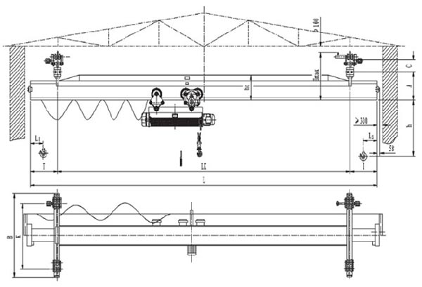
12. Sketch
Application of motor-driven single beam overhead crane
Manufacturing: Single-beam bridge cranes are often used in manufacturing industries such as mechanical processing, automobile manufacturing, and metal product production for material handling, workpiece assembly, and equipment maintenance. They can efficiently and accurately transport small and medium-sized workpieces to improve production efficiency.
Warehousing and logistics: In warehouses and logistics centers, single-beam bridge cranes are used to transport and stack goods, especially in storage environments with limited space. Effectively utilize space, simplify material handling processes, and reduce the labor intensity of manual operations.
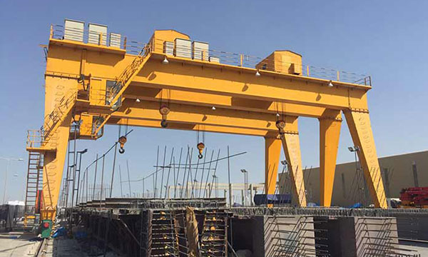
Construction industry: Used for material lifting and handling at construction sites, such as the transportation of building materials such as steel bars and formwork. The structure is light, the installation is simple, and the adaptability is strong, and it can be used in more complex construction environments.
Power industry: In the construction, maintenance, and operation of power facilities, single-beam bridge cranes are used to transport heavy equipment such as transformers and motors. Ensure the safe installation and maintenance of equipment and reduce the risk of manual operation.
Steel structure manufacturing: In steel structure manufacturing companies, single-beam bridge cranes are used for the handling, cutting, and assembly of steel components. Able to handle longer and heavier steel structure components to ensure production efficiency and process accuracy.
Advantages of motor-driven single beam overhead crane
Light weight: The single-beam bridge crane has a light weight, which reduces the load requirements on the building structure and can be installed and used in a relatively light factory structure. It is suitable for factories or workshops with limited building load-bearing capacity.
High space utilization: Since there is only one main beam, the height of the single-beam bridge crane is relatively low, which can better utilize the effective space of the factory, so that the hook can be close to the maximum height of the working area. It is suitable for occasions where space is limited and height needs to be maximized.
Strong adaptability: The single-beam bridge crane can be customized according to user needs and is suitable for different spans and lifting weight ranges, with strong adaptability. It is suitable for various industrial production lines, warehousing and logistics, equipment installation and other occasions.
High safety: Equipped with various safety devices, such as limit switches, overload limiters, wind protection devices, etc., it can ensure the safe operation of the equipment and reduce the probability of accidents. It is suitable for operating environments with high safety requirements.
Easy maintenance: Due to the simple structure and few components, the maintenance workload is small, the maintenance cost is low, and spare parts are easy to obtain. It is suitable for production lines or equipment that need to work continuously for a long time.
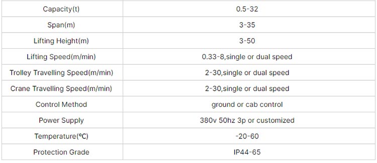
Main technical data
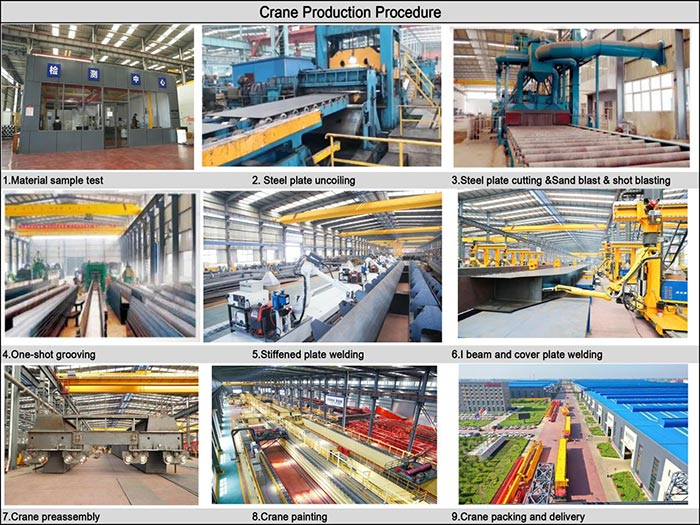
Crane production procedure
1. Demand Analysis and Design: Communicate with customers to understand their operating environment, load requirements, working frequency and other requirements. According to the requirements, design the overall plan of the crane, including the main beam, end beam, trolley, lifting system and other major components. Carry out detailed structural design to ensure structural strength and stability.
2. Material procurement: Purchase steel, aluminum alloy, transmission components, electrical components, etc. required for manufacturing cranes. According to design requirements, purchase standardized components such as motors, reducers, brakes, etc. Carry out quality inspection on purchased materials and components to ensure compliance with standards and design requirements.
3. Manufacturing and processing: Cut, weld and process steel to manufacture main beams and end beams. Manufacture components such as the frame, guide wheels, lifting devices of the trolley. Produce or assemble various components of the electrical control system, including contactors, relays, sensors, etc. Weld steel structure components to ensure connection strength and stability. Perform mechanical processing on components, such as drilling, milling and turning, to ensure the size and accuracy of components. Paint or coat components to protect steel from corrosion and wear.
4. Assembly: Assemble the main beam, end beam, trolley, lifting system and other components according to the design drawings. Connect the electrical control system to the mechanical components, including cable routing, wiring and debugging. Perform preliminary system debugging, check the coordination and function of each component, and ensure the normal operation of the system.
5. Testing: Perform static load test to check the load-bearing capacity and stability of the crane under static conditions. Perform dynamic operation test to check the performance of the crane in actual operation, including lifting, lowering, running speed, etc. Test the functions of various safety devices, such as limit switches, overload protection, sound and light alarm systems, etc.
6. Inspection and acceptance: Conduct a comprehensive inspection of the manufacturing and assembly quality of the crane to ensure compliance with design standards and technical requirements. Perform functional acceptance with the customer to confirm that the performance and functions of the crane meet the customer’s needs.
Global Market

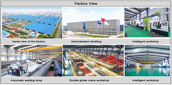
Workshop view
The company has installed an intelligent equipment management platform, and has installed 310 sets (sets) of handling and welding robots. After the completion of the plan, there will be more than 500 sets (sets), and the equipment networking rate will reach 95%. 32 welding lines have been put into use, 50 are planned to be installed, and the automation rate of the entire product line has reached.