

Description
Warning: mysqli_query(): (HY000/1194): Table 'wp_options' is marked as crashed and should be repaired in /www/wwwroot/excelcrane.com/wp-includes/class-wpdb.php on line 2349
Warning: mysqli_query(): (HY000/1194): Table 'wp_options' is marked as crashed and should be repaired in /www/wwwroot/excelcrane.com/wp-includes/class-wpdb.php on line 2349
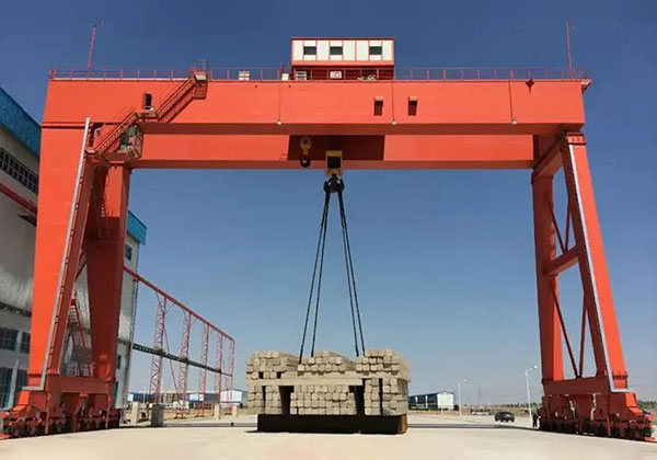
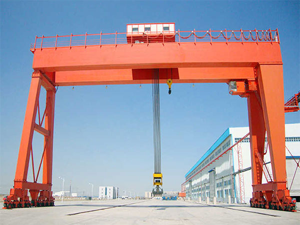
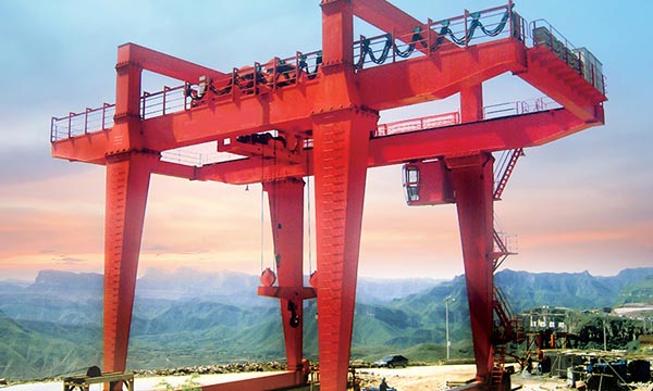
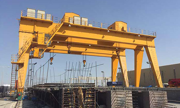
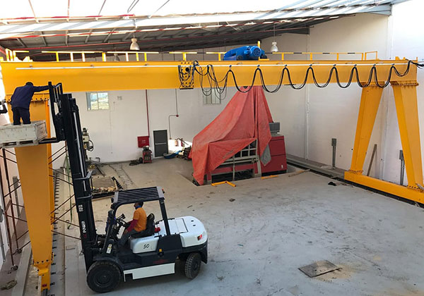
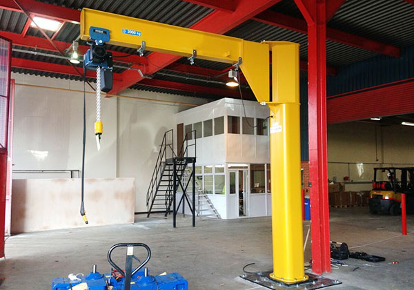
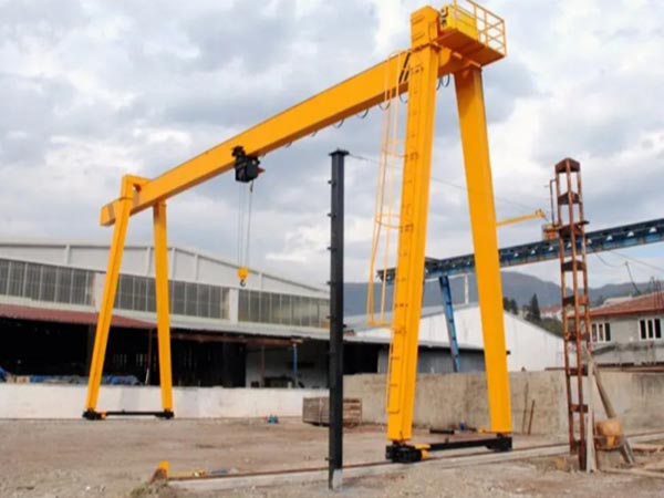
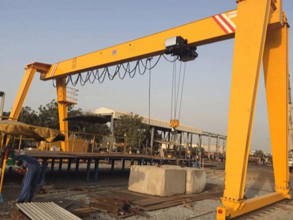
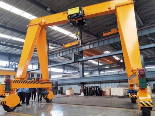
The main beam of this type of crane is a single-beam structure, usually made of I-beam or box beam, with good load-bearing capacity and rigidity. The legs are supported on the ground to ensure the stability of the crane. It is usually divided into rigid legs and flexible legs. The walking mechanism includes a walking wheel set and a drive device, which is responsible for the horizontal movement of the crane on the track. The lifting mechanism consists of an electric hoist or a lifting device, which is responsible for the lifting and lowering operations of the object. The control system usually includes an electrical control cabinet, a handle or a remote control to control the various operations of the crane.
The single-beam gantry crane moves along the track through its walking mechanism, and the lifting mechanism is responsible for lifting and lowering objects. The operator commands the crane to complete the handling task through the control system.
The single-beam structure is simple in design and easy to install and maintain. It can adapt to a variety of working environments, such as indoors or outdoors, and different spans and lifting heights can be designed according to needs. Compared with double-beam cranes, single-beam gantry cranes have lower manufacturing costs and are suitable for use by small and medium-sized enterprises. The equipped control system is simple to operate and can achieve precise lifting and handling.
Single-beam gantry cranes are suitable for places such as warehouses, cargo yards, workshops, ports, etc. where heavy objects need to be frequently moved, and are especially suitable for the movement of small and medium-sized materials. According to different usage requirements, the specifications of single-beam gantry cranes such as lifting capacity, span, lifting height, operating speed, etc. can be customized.

Components of single main beam hanger gantry crane
1. Main girder
The main beam usually adopts I-beam or box beam structure. The I-beam main beam has a simple structure and is suitable for small and medium-sized cranes, while the box beam has higher strength and rigidity and is suitable for cranes with larger tonnage. The main beam is generally made of high-strength steel and has good fatigue resistance and deformation resistance, ensuring stability and safety in long-term use.
The main beam can be designed as a box beam or an I-beam. The box beam is usually welded from four steel plates to form a closed box structure. This design improves the torsional rigidity and bending resistance of the main beam and is suitable for occasions requiring a large lifting weight. The I-beam consists of two upper and lower flange plates and a web plate, which is suitable for small and medium-sized cranes, with a light structure and low cost.
The main beam carries the load of the entire crane, including the weight of the lifting mechanism, slings and the objects being hoisted. Therefore, the strength and rigidity of the main beam must meet the design requirements to ensure safe operation under rated load. In order to ensure that no significant deformation occurs under heavy load, the bending and torsion resistance needs to be considered when designing the main beam. For large single-beam gantry cranes, box-type main beams can provide better anti-deformation capabilities.
The deadweight of the main beam directly affects the overall operating stability of the crane. Reasonable weight distribution design can reduce the load on the walking mechanism and track and extend the service life of the equipment.
2. Lifting System
The lifting system of a single-beam gantry crane usually includes the following main parts:
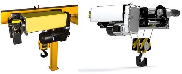
- Electric hoist: This is the core component of the lifting system, responsible for lifting and lowering objects through wire ropes or chains. Electric hoists include motors, reducers, drums, wire ropes or chains, hook heads, etc.
- Wire ropes or chains: used to carry and transmit lifting loads. Wire ropes are usually used for lifting of larger tonnage, while chains are used for smaller tonnage.
- Hook: A device that connects objects to the lifting mechanism, usually made of high-strength steel, with anti-falling and rotation functions.
- Limit switch: A device used to control the lifting height. When the hook or sling reaches the set highest or lowest position, the limit switch will automatically stop the lifting or lowering operation to prevent over-winding or over-releasing.
- Electric control system: Including control boxes, buttons, remote controls, etc., used to control the start, stop, lifting and speed adjustment of electric hoists.
3. End Carriages
The end beam is usually made of high-strength steel with good rigidity and load-bearing capacity. The shape and size of the end beam will be customized according to the design requirements of the crane. A travel wheel group, including a driving wheel and a driven wheel, is installed under the end beam, which is responsible for the movement of the crane on the track. The travel wheel is usually made of wear-resistant materials to extend the service life.
The drive device is usually installed at one end of the end beam, including components such as a motor, a reducer, and a brake. The drive device drives the crane to move along the track through the drive wheel. Buffer devices are usually equipped at both ends of the end beam to prevent the crane from colliding hard with the end of the track during movement, reduce the impact force, and protect the crane and the track.
As an important part connecting the main beam and the travel mechanism, the end beam is fixed to both ends of the main beam by bolts or welding. The end beam ensures that the crane can move stably horizontally along the track through the travel wheel group and drive device below it to cover the entire operating area.
The end beam usually adopts a box structure or an I-beam structure to ensure that it will not deform or break when carrying heavy objects. In order to ensure that the crane runs smoothly on the track, the manufacturing and installation of the end beam requires high precision to avoid travel deflection or track jamming due to alignment errors.

4. Crane traveling mechanism
The crane running mechanism usually consists of the following main parts:
- Driving device: including motor, reducer, coupling, etc., responsible for providing power for the horizontal movement of the crane.
- Traveling wheel group: installed under the end beam of the crane, composed of driving wheel and driven wheel, the traveling wheel group rolls along the track to realize the movement of the trolley of the crane.
- Track: The steel rails laid on the ground, usually standard steel rails or customized tracks, provide the path for the trolley to run.
- Braking device: including brakes, limit switches, etc., to control the start, stop and emergency braking of the trolley to ensure safe operation.
- Buffer device: installed at both ends of the trolley, used to absorb impact force when the trolley approaches the end of the track to avoid hard collision.
5. Trolley traverling mechanism
The operator starts the trolley running mechanism through the control system, the motor drives the reducer, the power output by the reducer is transmitted to the drive wheel, and the drive wheel rolls along the track, thereby driving the trolley to move. When the trolley needs to stop or in an emergency, the braking device will take effect immediately, and the brake will quickly decelerate and stop the trolley.
The trolley running mechanism generally uses a three-phase asynchronous motor as the power source, and the motor power is selected according to the load capacity and speed requirements of the trolley. The reducer is connected between the motor and the drive wheel to convert the high speed of the motor into a low-speed and high-torque output suitable for the movement of the trolley. The coupling is used to connect the motor and the reducer to ensure the smoothness of power transmission and compensate for installation errors.
Regularly check the wear of the running wheels, the operating status of the motor and the reducer, the sensitivity of the braking device, etc., to ensure the normal operation of the trolley running mechanism. Regularly add lubricating oil to the running wheel bearings, reducers and other components to reduce friction and extend service life. Ensure the cleanliness and flatness of the main beam track, and regularly check the wear and centering of the track to prevent jamming or derailment during the operation of the trolley.
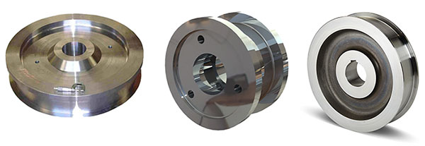
6. Crane wheel
The wheels of a single-beam gantry crane are generally divided into two categories: the driving wheel is connected to the drive device (such as an electric motor, a reducer), and is responsible for providing power to move the crane on the track. The driven wheel is not directly connected to the drive device, but is driven by the driving wheel to roll with it, playing a supporting and balancing role.
The wheel rim is the edge of the wheel, which is used to keep the wheel on the track and prevent derailment. The wheel rim is usually high and strong to cope with heavy loads and lateral forces. The wheel center is the central part of the wheel, which is connected to the wheel axle through a bearing to bear and transmit the load. The wheel center is generally designed to be solid or hollow, depending on the load requirements of the crane. The wheel surface is the part of the wheel that contacts the track, which is usually cylindrical or conical to ensure good contact with the track and reduce wear and sliding.
The wheel material is usually treated with quenching or other heat treatment processes to increase hardness and wear resistance, thereby extending the service life of the wheel. The wheel design must ensure smooth rolling on the track and reduce friction resistance and energy loss during operation. Self-lubricating materials or structures are added to some wheel designs to reduce friction and wear of the bearings and improve operating efficiency.
The wheels are usually mounted on the axles through rolling bearings. The bearings need to be well-fitted and lubricated to ensure that the wheels can rotate smoothly. When installing the wheels, ensure that they are aligned with the track and that the installation height is consistent to avoid unstable operation or track wear due to imbalance or deviation. The connection between the wheel and the axle needs to be tightened firmly to avoid looseness. At the same time, it needs to be debugged after installation to ensure smooth and unobstructed operation of the wheel.
7. Crane hook
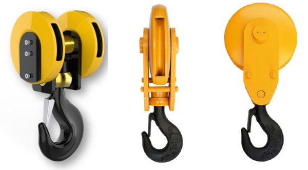
The hooks of single-beam gantry cranes are usually divided into the following types:
- Single hook: the most common type, suitable for lifting ordinary heavy objects, with a simple structure and easy to use.
- Double hook: used to lift long or irregular objects, it can balance the load and reduce swaying.
- Swivel hook: with a swivel device, allowing the hook to rotate freely during the lifting process, which is convenient for aligning the hanging point of the load.
The hook is generally made of high-strength alloy steel or forged steel, which has the following characteristics:
- High strength: able to withstand huge tensile and impact forces, ensuring that no breakage or deformation occurs under high loads.
- Wear resistance: The hook is often in contact with wire ropes, chains and load surfaces. Materials with high wear resistance can extend the service life of the hook.
- Toughness: The hook material needs to have good toughness to prevent brittle fracture under sudden loads or impacts.
8. Motor
According to the different application requirements of single-beam gantry cranes, the commonly used motor types include:
- Three-phase asynchronous motor: This is the most common type of motor, which is widely used in various industrial cranes due to its simple structure, convenient maintenance and low cost.
- Variable frequency speed regulating motor: This motor can be used with a frequency converter to achieve smooth starting and stepless speed adjustment, and is suitable for occasions with high requirements for operating speed and precise positioning.
- Explosion-proof motor: It is suitable for cranes working in environments with flammable and explosive gases or dust. Explosion-proof measures are added to the design to ensure safe operation.
- Braking motor: It has an integrated electromagnetic braking device, which can quickly brake after the motor is powered off, ensuring that the crane can stop quickly or maintain its position unchanged.

9. Sound and light alarm system & limit switch
① Sound and light alarm system
- Operation warning: Before the crane starts or stops, the sound and light alarm system will send out warning signals in advance to alert the surrounding personnel to prevent accidents.
- Fault alarm: When the crane fails (such as overload, overheating, etc.), the system will automatically send out sound and light alarms to notify the operator to take timely measures.
- Emergency notification: In emergency situations, such as unexpected power outages or mechanical failures, the system can send out continuous alarm signals to attract the attention of the operator and initiate emergency treatment.
② Limit switch
- Movement restriction: The limit switch detects the position of the crane components by mechanical or electronic means. When the components reach the set limit position, it automatically cuts off the power supply of the motor or issues a warning to prevent further operation.
- Collision prevention: During the operation of the crane’s trolley and car, the limit switch can prevent it from exceeding the track or colliding with other equipment.
- Over-lift protection: In the lifting mechanism, the limit switch can prevent the hook from lifting beyond the safe height, avoiding overwinding or hitting the upper limit.

10. Safety Devices
Overload protection device: The overload protection device is used to prevent the crane from overloading and protect the equipment and personnel.
Braking system: The braking system is used to ensure the stability of the crane when the motor is powered off or the operation is interrupted.
Safety buffer device: The safety buffer device is used to absorb the impact of moving parts and reduce damage to the equipment.
Electrical protection device: The electrical protection device is used to protect the motor and electrical system from electrical faults.
Safety alarm system: The safety alarm system is used to issue a warning when an abnormal situation occurs to ensure the safety of the operator.
11. Control Mode
Manual control: Manual control is the most basic control method, where the operator directly controls the movement of the crane through a manual operating device.
Ground control: The ground control method uses a ground control panel or control box to control the various functions of the crane through a wired connection.
Remote control: The remote control method allows the operator to control its movement from a location far away from the crane, improving operational safety and flexibility.
Automated control: The automated control method achieves automatic operation through a computer or PLC (programmable logic controller) system, and is usually used for operations that require high precision and repeatability.

12. Sketch

Application of single main beam hanger gantry crane
Warehouses and logistics centers: In warehouses and logistics centers, single-beam gantry cranes are used to move, load and unload, and stack various goods, such as raw materials, finished products, and packaging. They can be used to move goods up and down in overhead storage systems, helping to achieve efficient storage and retrieval management.
Manufacturing: Used to lift and move heavy machinery parts or processing equipment to ensure smooth production processes.
Construction sites: On construction sites, single-beam gantry cranes are used to move heavy construction materials such as concrete, steel, and building modules. Assist in the installation of large-scale construction equipment and structural parts to improve construction efficiency.
Ports and docks: In ports and docks, single-beam gantry cranes are used to load and unload containers and bulk cargo, supporting cargo handling and transportation at ports. Help load and unload cargo on ships and improve port operation efficiency.
Power and energy industry: In power plants and energy facilities, single-beam gantry cranes are used to lift and install large power generation equipment, transformers, and other heavy equipment. Used to move and position heavy parts during equipment overhaul and maintenance.
Advantages of single main beam hanger gantry crane
Single-girder gantry cranes have significant advantages in various industrial and logistics applications due to their unique design and functions. The following are the main advantages of single-girder gantry cranes:
Simple structure: The design of single-girder gantry cranes is relatively simple, mainly consisting of a single main beam, legs, end beams, operating mechanism and lifting system. The simple structure makes it easier to manufacture, install and maintain.
High space utilization: Since the operating mechanism and main beam of the crane are located on the upper part of the crane, the space below can be effectively utilized to facilitate the handling and storage of goods.
Strong flexibility and adaptability: Single-girder gantry cranes can be used in a variety of environments, such as indoor warehouses, workshops, docks, etc., and can adapt to different working conditions and needs.
Easy operation: Since the operating system is usually intuitive, it is easy for operators to get started, reducing training costs and time.
High safety: The design has support legs and a stable foundation, which provides high stability and ensures that the equipment is safe and reliable during lifting and moving.

Main technical data

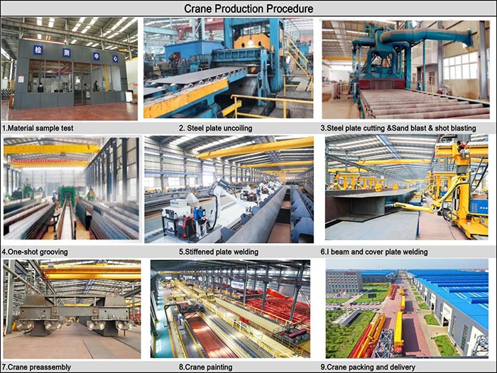
Crane production procedure
Demand analysis: Understand the specific needs of customers, including the working environment, lifting capacity, span and other specific requirements of the crane. Formulate technical specifications according to the needs, including lifting height, load capacity, operating speed, etc.
Design: Carry out structural design of single-beam gantry crane, including main beam, outriggers, end beams, trolley, operating mechanism and other parts. Draw detailed design drawings and engineering drawings, including the size, material and assembly method of each component.
Material procurement: Select suitable materials such as steel, aluminum alloy, etc. according to design requirements to ensure the strength and durability of the materials.
Parts manufacturing: Cut steel into required sizes, and perform welding, drilling, processing and other operations to manufacture main beams and end beams. Weld each steel component to ensure that the welding quality meets the standards. Manufacture various components of the trolley operating mechanism, such as wheels, drive devices, brackets, etc. Assemble the components of the trolley to ensure that it can run smoothly. Produce and assemble lifting motors, reducers, drums, hooks and other components. Assemble the various components of the lifting system to ensure that it can work properly.
Assembly: Connect and weld the main beam to the legs to ensure stability and strength. Install the end beam, fix and adjust it. Install the trolley on the main beam to ensure smooth operation on the main beam. Install the operating mechanism of the trolley and the trolley to ensure normal operation. Install the hoist and related equipment on the main beam, connect the cables and debug. Install electrical components such as motors, control cabinets, switches, sensors, limit switches, etc.
Testing and adjustment: Check the installation and connection of all components and make necessary adjustments. Perform a no-load operation test to check whether the various functions of the crane are normal and ensure that there are no mechanical failures. Perform a test under the specified load to check the performance and stability of the lifting system, operating mechanism and electrical system. Test all safety devices, such as limit switches, overload protection devices, sound and light alarm systems, etc., to ensure their normal function.
Global Market

Workshop view
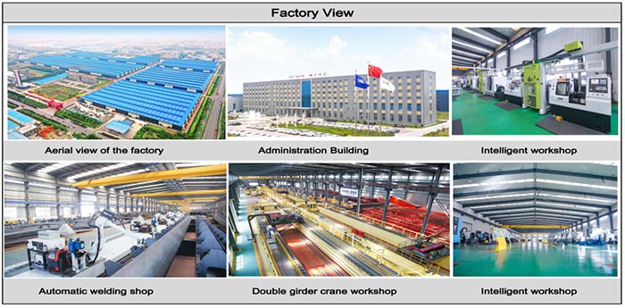
The company has installed an intelligent equipment management platform, and has installed 310 sets (sets) of handling and welding robots. After the completion of the plan, there will be more than 500 sets (sets), and the equipment networking rate will reach 95%. 32 welding lines have been put into use, 50 are planned to be installed, and the automation rate of the entire product line has reached.