Description
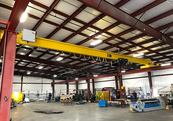
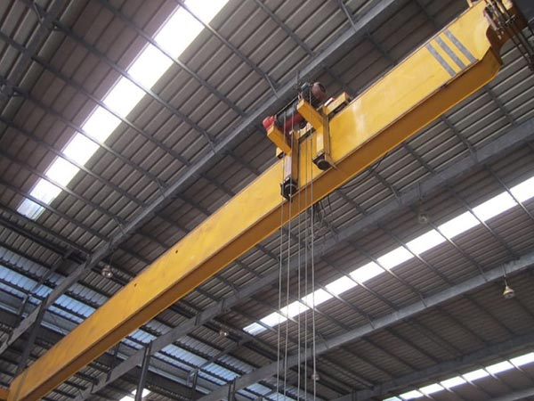
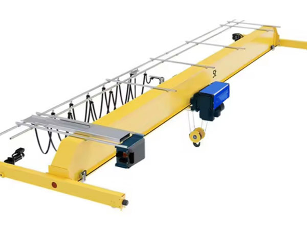
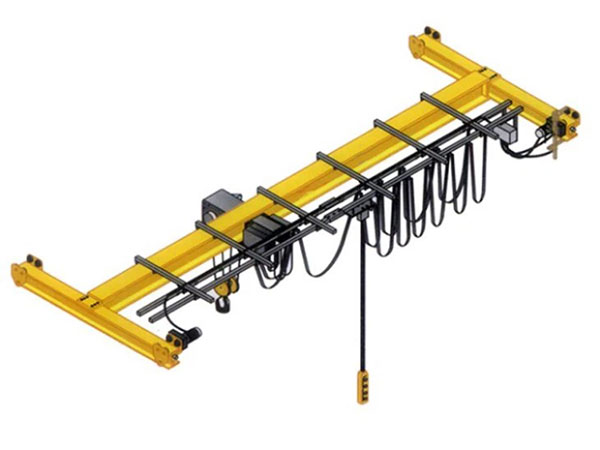
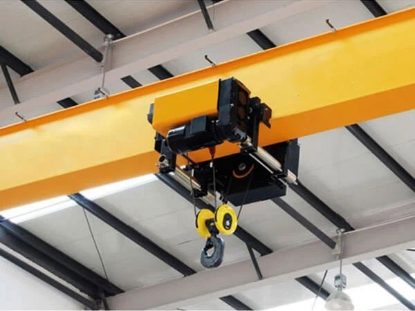
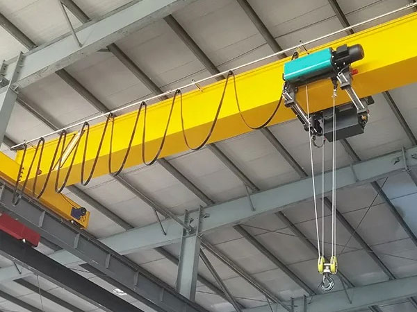
1. A single-girder bridge crane is a bridge-type lifting equipment composed of a single main beam, two end beams, and a lifting and operating mechanism. It is usually installed on the roof or elevated of a factory or workshop and is suitable for indoor and outdoor material handling operations.
2. The main beam is the main load-bearing structure of the crane, usually made of I-beam or box beam. It spans between two parallel rails and carries the weight of the hoisting mechanism and spreader. The end beams are connected to both ends of the main beam and move parallel to the track. Wheels are installed on the end beams, which are responsible for the lateral movement of the crane on the track.
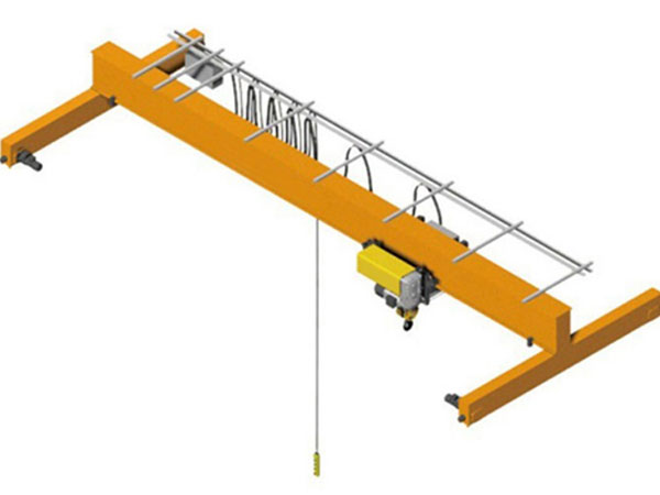
3. The single-beam design makes for a simple structure, low manufacturing costs, and easy maintenance. Due to its lightweight structure, the installation process of a single-girder overhead crane is relatively simple and is suitable for quick installation in an existing factory or workshop. Single-girder bridge cranes can be operated via ground handles, cab controls or wireless remote controls to adapt to the needs of different working environments.
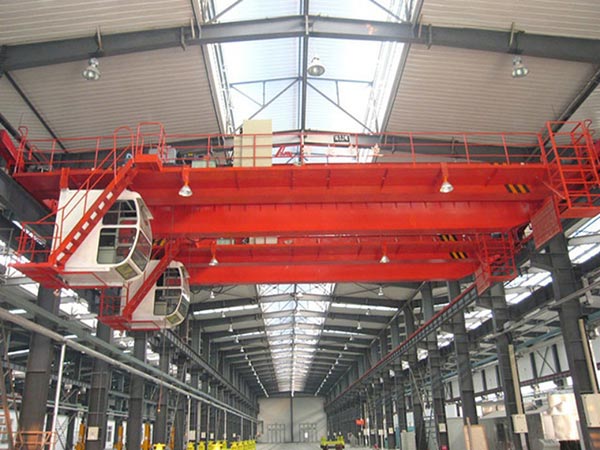
4. Compared with double-girder cranes, single-girder bridge cranes have lower manufacturing and installation costs and are suitable for the material handling needs of small and medium-sized enterprises. The compact design of single-girder overhead cranes enables them to operate at lower building heights, saving vertical space in the factory building.
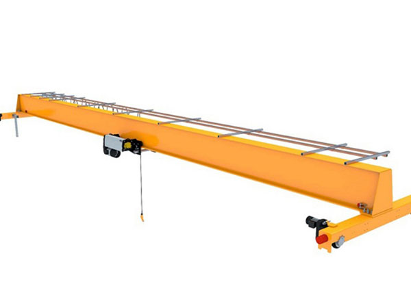
5. Single-girder bridge cranes have become important handling equipment in many fields such as industrial production, warehousing logistics, and maintenance operations due to their simple structure, low cost, and flexible operation. Its diverse applications and customizable design enable it to meet material handling needs under various working conditions.
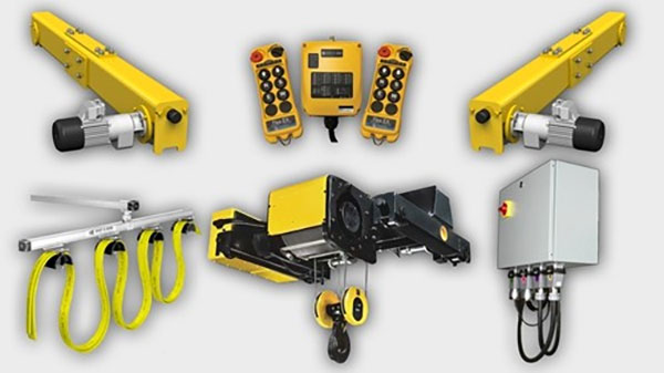
Components of electric single girder crane
1. Main girder
- I-shaped main beam is the most common main beam structure, using I-beam (I-shaped steel) as the main beam. Due to its simple structure and high strength, the I-shaped main girder is widely used in small and medium-sized single-girder overhead cranes. The upper and lower flange plates and web plates of the I-shaped main girder jointly carry the load and are suitable for cranes with small span and lifting capacity.
- The main girder of single-girder bridge crane is usually made of high-strength low-alloy steel or carbon structural steel, such as Q235B, Q345B, etc. These steels have good welding and mechanical properties and can meet the strength and rigidity requirements of cranes when carrying heavy loads. For single-girder bridge cranes used outdoors or in harsh environments, the main girder may use weather-resistant steel to improve its corrosion resistance and extend its service life.
- After the steel plates of the single-girder bridge crane are precisely cut by a CNC cutting machine, they are spliced into the basic structure of the main girder through a welding process. The quality of welding directly affects the strength and service life of the main beam, so the welding process needs to be strictly controlled to ensure that the weld is defect-free. After welding is completed, the main beam needs to be corrected to ensure its straightness and dimensional accuracy. The corrected main beam is usually pre-assembled to check the fit with other components.
- In order to reduce the dead weight and improve the operating efficiency of the crane, the main beam usually adopts lightweight design to reduce the weight as much as possible while ensuring the strength. Since the crane will bear repeated loads during operation, the main beam was designed with fatigue strength in mind to ensure that it will not suffer fatigue damage during long-term use.
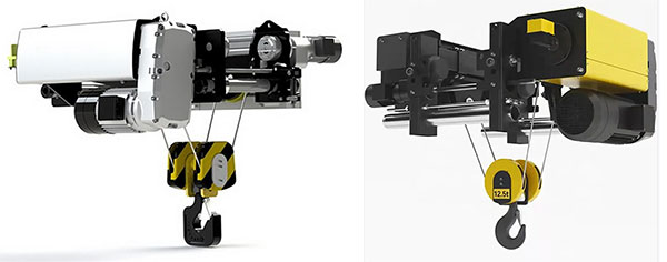
2. Lifting System
- Electric hoist: This is the most common lifting equipment used in single-girder bridge cranes. Electric hoists are usually installed below the main beam and drive wire ropes or chains to lift materials vertically. Electric hoists are divided into two types: wire rope electric hoists and chain electric hoists. The former is more suitable for applications with larger lifting capacities.
- Wire rope or chain: used to connect the hook to the lifting device of the electric hoist. Steel wire ropes have high strength and flexibility and are suitable for larger spans and heavy loads; ring chains are suitable for shorter spans and lighter loads.
- Hook: The hook is connected to the electric hoist through a wire rope or chain and is used to directly mount items. The hook usually has a safety buckle to prevent the hanging object from accidentally slipping off.
- Pulley block: Improve the efficiency of the lifting system by changing the direction of the wire rope, reduce the direct force on the electric hoist, and enable it to lift larger objects.
- Brake: Installed inside or outside the electric hoist, it is used to control the stopping and maintaining position of the lifting system to prevent the risk of falling objects in the event of a power outage or malfunction.
- Rope guide (optional): The rope guide is used to prevent the wire rope from being wound unevenly on the drum, ensuring the stable operation of the lifting system and extending the service life of the wire rope.
The hoisting system of a single-girder bridge crane is the core functional part of the entire equipment, which directly affects its operating efficiency and safety. Through precise design, strict manufacturing processes and complete safety protection devices, the lifting system can operate safely and stably under various working conditions. Regular maintenance and upkeep are key to ensuring long-term and efficient operation of the lifting system.
3. End Carriages
- The end beam and main beam are connected by welding or bolting to form the overall structure of the crane. The design of the connection must ensure the stability and load-bearing capacity of the structure.
- Wheel axles are installed on the end beams, and the wheel axles connect the wheels to enable the crane to move horizontally along the track. The design and manufacturing of the wheel axle directly affects the smooth operation and durability of the crane.
- The end beam is usually made of high-strength steel, such as Q235B, Q345B, etc., which has good welding performance and strength and can withstand the load of the crane. End beams used outdoors or in harsh environments may be constructed of weather-resistant steel to increase their resistance to corrosion and extend their service life.
- End beams need to be designed for strength and stiffness to carry the main beam and its load. Structural designs often incorporate reinforcing ribs or reinforcement bars to increase the strength of the end beams. Wheels and wheel axles will be subject to wear during use, so the end beam is designed with wear resistance in mind to ensure long-term stable operation of the wheels and wheel axles.
4. Crane traveling mechanism
- Crane frame: The crane frame is the main structural part that supports the entire operating mechanism and is usually made of welded steel structure. The axles and wheels are installed on the frame and support the lifting mechanism and other related equipment.
- Wheel axle: The wheel axle connects the crane frame and wheels and is the core component that converts the motion of the cart into horizontal movement along the direction of the main beam. Wheel axles need to be designed with load, strength and wear resistance in mind.
- Wheels: The wheels are installed on the wheel axles and contact the rails on the main beam to enable the cart to move smoothly. Wheels are typically made from high-strength steel and may feature a bearing system to reduce friction and wear.
- Driving device: The driving device is used to provide power to the cart so that it can move horizontally along the main beam. Common drive devices include electric motors, reducers and transmissions.
- Braking system: The braking system is used to control the movement of the cart to ensure that it can stop stably when it needs to stop or slow down. Braking systems usually include electromagnetic brakes or mechanical brakes.
- Guide device: The guide device helps the cart maintain the correct position on the main beam track and prevents the cart from deflecting or derailing during operation. Common guide devices include guide rails, guide wheels or sliders.
The crane operating mechanism of a single-girder bridge crane is the core component that ensures the horizontal movement of the crane along the main beam. Its design and maintenance directly affect the operating efficiency and safety of the crane. Through reasonable design, precise manufacturing and regular maintenance, the trolley operating mechanism can operate stably and efficiently under various working conditions, ensuring the overall performance and safety of the crane.
5. Trolley traveling mechanism
- The driving device of the trolley operating mechanism transmits power to the wheels through the motor and reducer, allowing the trolley to move horizontally on the main beam track. The rotation of the motor is converted into the rotation of the wheels through the transmission device, thereby realizing the movement of the car.
- When it is necessary to stop or decelerate, the braking system will start to generate braking torque, slow down the rotation speed of the wheels, and ensure the smooth parking of the car. The control of the braking system can be achieved through an electrical control system or manual operation.
- The guide device helps the trolley maintain the correct position on the main beam track and prevents movement deviation caused by wheel or track misalignment. Guides usually require regular inspection and maintenance to ensure they are working properly.
- The load capacity of the trolley’s operating mechanism determines the maximum load it can bear, and is usually designed based on the crane’s lifting capacity and working environment. The load capacity needs to be higher than the maximum working load to ensure safety.
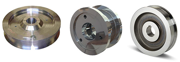
6. Crane wheel
The wheel body is the main load-bearing part of the wheel and is usually cast or machined from high-strength steel. The design of the wheel body needs to ensure sufficient strength and wear resistance to withstand the load of the crane. Wheels are usually equipped with bearings to reduce friction between the wheel and the wheel axle and improve operating efficiency. Bearing selection requires consideration of load, operating speed and environmental conditions. The wheels are connected to the trolley frame through wheel axles. The design and manufacture of the wheel axles need to ensure their strength and rigidity to support the overall load of the wheels and crane.
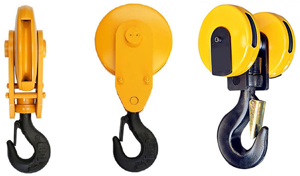
7. Crane hook
The hook of a single girder overhead crane is one of the key components of the crane and is used to lift and move loads. The hook system needs to be high-strength, safe, reliable and easy to operate. The following is a detailed introduction to the composition of the hook of a single-girder bridge crane:
- Hook body: The hook body is the main part that carries the load and is usually made of high-strength alloy steel or carbon steel. Its design must ensure sufficient strength and toughness to withstand loads under various working conditions.
- Hook body: The hook body is the main part of the hook. It is usually shaped like a curved hook and is used to hook and fix the load. The design of the hook body must ensure that it can firmly hang the hanging objects and prevent the hanging objects from slipping.
- Hook mouth: The hook mouth is the part of the hook that contacts the load. It usually has an opening or groove for hanging objects. The design of the hook mouth needs to ensure that it can hold the hanging object stably and prevent the hanging object from falling during the lifting process.
- Safety devices: Hooks are usually equipped with safety devices, such as safety locks, rope clamps, etc., to ensure the safety of the load during lifting. The safety device prevents the load from accidentally slipping and ensures the safety of the operator.
8. Motor
- The power of an electric motor determines the driving force it can provide. The power size needs to be selected according to the load capacity and working requirements of the crane. Typically, motor power ranges from a few kilowatts to tens of kilowatts.
- The voltage level of the motor needs to match the power system. Common voltage levels include three-phase AC voltages such as 380V and 415V. The speed of the motor determines the rotation speed of its output shaft, which affects the operating speed of the crane. The rotation speed can be fixed or adjusted through a speed regulating device. The insulation level of a motor determines the temperature range and environmental conditions it can withstand. Common insulation grades include Class B, Class F, etc.
- The operating status of the motor needs to be checked regularly, including current, voltage, temperature and noise. Make sure the motor is running normally without abnormal vibration or noise. And regularly check and replace the bearing lubricating oil of the motor to keep the bearings in good lubrication condition. At the same time, keep the outside of the motor clean to prevent the accumulation of dust and dirt from affecting heat dissipation and operating performance.

9. Sound and light alarm system & limit switch
- During the operation of the crane, the audible and visual alarm system will emit alarm sounds and flashing lights to warn operators and surrounding people of the working status of the crane. It is mainly used to remind personnel that the equipment is running or has abnormal conditions. In the event of a fault or abnormal situation (such as overloading, overheating, etc.), the sound and light alarm system will automatically activate to prompt the operator to take timely measures.
- The limit switch is used to limit the movement range of the crane and prevent the crane from exceeding the set safety range during lifting or movement. For example, to prevent a trolley or trolley from exceeding a predetermined position at the end of the track.Prevent collisions between various components of the crane (such as hooks, trolleys, trolleys, etc.) and protect equipment and loads.
- An audible and visual alarm system can be a high-volume buzzer or siren that emits a loud sound. The loudness of the sound can usually be adjusted to suit different work environments. It can also be a flashing LED light or flash light, installed in a conspicuous position of the crane. The color and flashing pattern of the warning light are used to indicate different warning states (e.g. red flashing indicates emergency, yellow flashing indicates warning status).
- Limit switches should be installed at key locations of the crane, such as the upper and lower ends of the lifting mechanism, the end point of the moving mechanism, etc. When installing, ensure that it can accurately detect the set limit. Adjust the triggering point of the limit switch according to the working range of the crane to ensure that it triggers the switch at the correct position. The actual range of motion of the load and the design requirements of the equipment need to be considered when adjusting.

10. Safety Devices
The safety settings of single-girder overhead cranes are crucial to ensure the safety of the equipment and operators during use. The following is a detailed introduction to the safety settings of single-girder bridge cranes:
- Overload protection: Prevents the crane from operating beyond the rated load, protects equipment from damage, and ensures operator safety.
- Limit switch: Limit the movement range of the crane to prevent exceeding the safe range or causing a collision.
- Sound and light alarm system: sounds an alarm during crane operation to remind operators and surrounding people to pay attention.
- Emergency stop device: In the event of an emergency, the power to the motor is quickly cut off and all movements of the crane are stopped.
- Electrical protection device: protects the electrical system from overload, short circuit, leakage and other faults.
- Structural strength inspection: Ensure that the structural components of the crane (such as main beams, outriggers, hooks, etc.) will not deform or break when subjected to load.
- Safety signs and warnings: Remind operators and surrounding people to pay attention to safety and prevent accidents.
11. Control Mode
The control methods of single-girder bridge cranes mainly include the following:
- Manual control: Control the movement of the crane by manually operating the controller or operating lever. Suitable for simple operating environments and smaller loads.
- Electric control: Use an electric control system to operate the crane, including buttons, switches, rockers, etc. This approach provides more precise control and greater security.
- Remote control: Using a wireless remote control device to operate the crane, the operator can control it from a distance away from the crane, improving safety and flexibility.
- Automatic control: Use a computer control system to automatically perform tasks according to preset programs. This method is suitable for highly repetitive tasks and improves work efficiency and accuracy.
- Hybrid control: combines the characteristics of manual, electric, remote control and automatic control to perform flexible operations according to specific needs
- Ultimately, the control mode for a casting steel overhead crane depends on the specific needs of the application, and a variety of different control modes may be used depending on the situation.
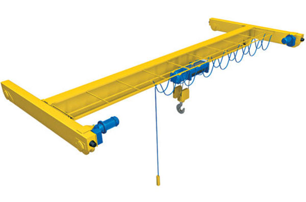
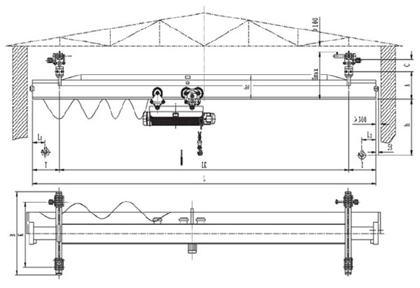
12. Sketch
Application of electric single girder crane
Single girder overhead cranes provide important functions in a variety of application scenarios, mainly including:
1. Manufacturing: Used to move and lift heavy objects required in the manufacturing process, such as machine parts, molds and tools. Able to efficiently handle, hoist and move various types of heavy objects and materials to improve work efficiency.
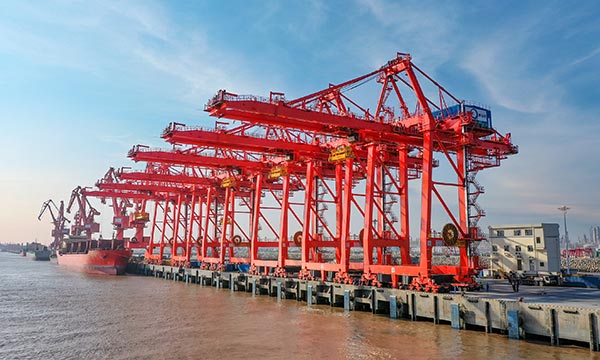
2. Warehousing and logistics: moving and stacking goods in the warehouse to improve storage density and pickup efficiency. Carry out loading and unloading operations in the yard or warehouse to optimize space utilization.
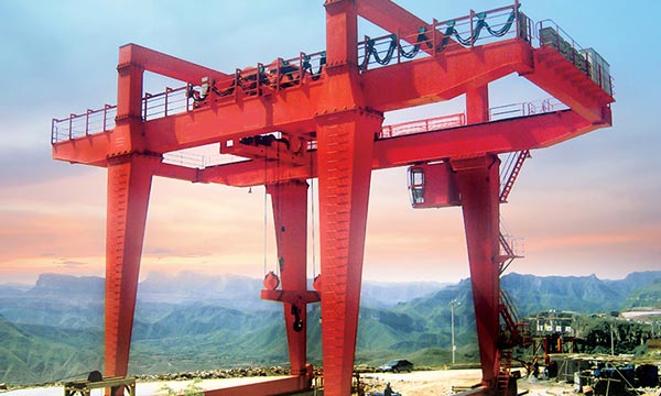
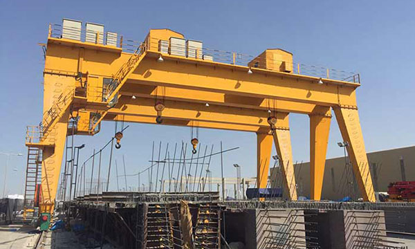
3. Construction sites: Used for lifting, transporting and placing building materials such as bricks, steel and concrete elements. Provide stable lifting support during the construction process and improve construction efficiency.
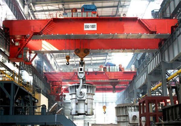
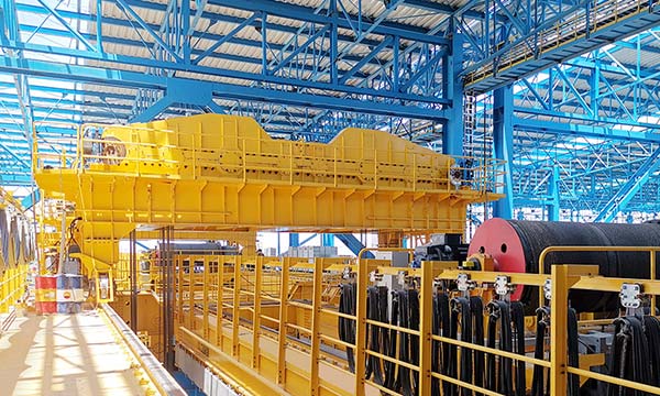
4. Steel Industry: Used in steel plants to handle heavy materials such as steel and castings. Support material movement and equipment maintenance on the production line.
5. Mining and Metallurgy: For the handling and processing of ores, metals and other mineral resources.Support equipment installation and maintenance within the mine.
Advantages of electric single girder crane
Single girder overhead cranes have many advantages that make them very popular in various industrial applications. Key benefits include:
1. Small space occupied: Since there is only one main beam, it takes up less space than a double-girder bridge crane, making it suitable for places with limited space.
2. High flexibility: It is suitable for a variety of scenarios, especially in smaller workshops and warehouses, and can provide efficient material handling solutions.
3. High lifting height: It is suitable for working environments that require high lifting height and can effectively utilize the vertical space of the factory building.
4. Stable operation: The crane operates smoothly and has high safety and reliability.
5. Wide range of applications: Can be used in a variety of industrial applications, including handling, loading and lifting of light and medium loads.
6. Easy installation: The installation and disassembly of single-girder bridge cranes is relatively simple, and the construction period is short.
7. High cost-effectiveness: low initial investment and operation and maintenance costs make it cost-effective.
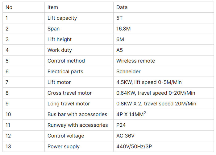
Main technical data
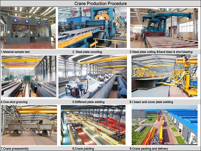
Crane production procedure
The process of producing a single-girder overhead crane usually includes the following main steps:
1. Design and planning: Determine the crane’s usage needs, working environment and load requirements. Design the structure, size and function of the crane and formulate technical solutions. Perform detailed engineering design, including mechanical design, structural design, and electrical control design.
2. Material procurement: According to the design requirements, purchase the required steel materials, welding materials, electrical components and other accessories. Conduct quality inspections on purchased materials to ensure compliance with design standards and requirements.
3. Processing and Fabrication: Cutting, welding and assembling main beams to ensure structural strength and precision. Fabrication and processing of sub-frames, which often include the supporting and running components of a crane. Assemble electrical components such as motors, control systems, distribution boxes, etc. Make and install other components such as hooks, pulleys, braking systems and wheels.
4. Assembly and debugging: Preliminary assembly of main beams, auxiliary beams, crane wheels, drive systems and other main components.Install electrical systems including cables, switches, sensors, etc. Carry out functional testing and debugging to ensure the normal operation of various functions of the crane, including load testing, operational stability and safety system testing.
5. Quality inspection: Check welding quality, component assembly and overall structure to ensure compliance with design standards. Conduct comprehensive functional tests, including lifting, moving, braking and other operations to ensure stable equipment performance. Check safety devices and protective measures to ensure equipment meets safety standards.
6. Final adjustment and acceptance: Make necessary adjustments and optimizations based on test results to ensure that the equipment reaches its best working condition. Conduct acceptance inspection with users to ensure that the equipment meets the actual needs and specifications of users.
Global Market

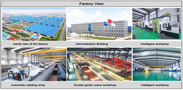
Workshop view
The company has installed an intelligent equipment management platform, and has installed 310 sets (sets) of handling and welding robots. After the completion of the plan, there will be more than 500 sets (sets), and the equipment networking rate will reach 95%. 32 welding lines have been put into use, 50 are planned to be installed, and the automation rate of the entire product line has reached.