
Description
Warning: mysqli_query(): (HY000/1194): Table 'wp_options' is marked as crashed and should be repaired in /www/wwwroot/excelcrane.com/wp-includes/class-wpdb.php on line 2349
Warning: mysqli_query(): (HY000/1194): Table 'wp_options' is marked as crashed and should be repaired in /www/wwwroot/excelcrane.com/wp-includes/class-wpdb.php on line 2349
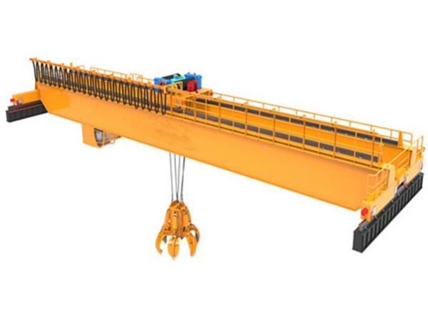
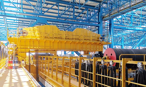
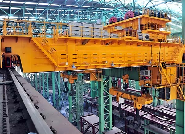
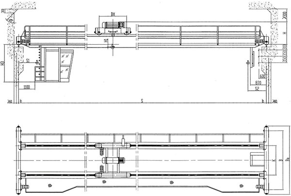
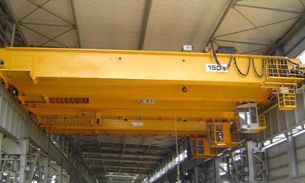
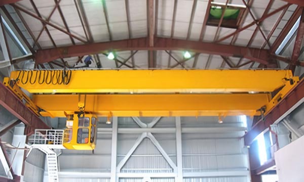
Overhead travelling cranes are composed of two parallel main beams. The main beams are generally box-type structures or I-beams, which have high rigidity and strength and can withstand large loads. The bridge spans the supporting structures on both sides along the track (such as the columns of the factory or special track brackets), and can move longitudinally along the track in the factory or in the open air. The hoisting trolley runs along the track of the main beam, carrying the hoisting equipment and the hoisting motor system, which can realize the horizontal and vertical movement of materials. This type of crane is equipped with electrical components such as motors, reducers, brakes, and control cabinets, and has the characteristics of easy operation and precise positioning.
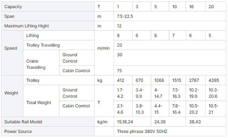
The lifting capacity of double-beam bridge crane is usually 5 tons to 500 tons, or even higher, and the specific parameters are customized according to customer needs. The span can reach tens of meters, and the common span range is between 10 meters and 40 meters. According to the requirements of the use environment, its lifting height can reach tens of meters, and the common range is 6 meters to 30 meters. The operating speed of the bridge crane, the operating speed of the hoisting trolley, and the lifting speed can be adjusted according to different working conditions.
The double-beam structure provides greater load-bearing capacity and higher stability, suitable for frequent and heavy material handling operations. Equipped with a variety of safety devices, such as limiters, overload protection, emergency stop buttons, etc., to ensure safe operation. Cranes of different specifications and functions can be customized according to different working conditions to meet special needs. The use of high-quality steel and advanced manufacturing technology ensures the long life and low maintenance requirements of the equipment.
Components of overhead travelling crane
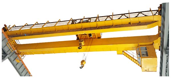
1. Main girder
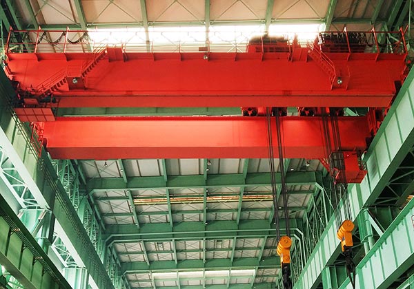
- The main beam of a double-beam bridge crane consists of two parallel beams, usually located on both sides of the crane’s bridge. This double-beam design provides greater load-bearing capacity and higher stability than a single-beam design. The main beam usually adopts a box-type structure, that is, a closed structure welded from steel plates. This design can effectively increase the rigidity and torsion resistance of the main beam, reduce deformation, and is suitable for high-load and long-span applications. In some application scenarios, the main beam can also adopt an I-beam structure. Although the I-beam main beam has a low manufacturing cost, its load-bearing capacity and rigidity are relatively weak, and it is generally used in small and medium-sized cranes.
- The main beam is generally made of high-strength low-alloy steel or carbon steel to ensure the load-bearing capacity and durability of the main beam. Commonly used steel models include Q235B, Q345B, etc. The manufacturing process of the main beam includes multiple steps such as steel cutting, assembly, welding, and machining. The welding quality is crucial to the overall strength and stability of the main beam, so automated welding equipment is required, and non-destructive testing is performed to ensure the welding quality.
- The main beam is the main load-bearing component of the crane, carrying the weight of the crane trolley, hoisting equipment and the hoisted object, and distributing this weight to the crane’s supporting structure through the bridge. There is a track on the main beam for the hoisting trolley to move along the length of the main beam. The track is usually made of high-strength wear-resistant steel to ensure stability and durability during long-term use. The main beam needs to have good bending, shear and torsion resistance to cope with various complex stresses during the lifting process and ensure safety and stability under full load working conditions.
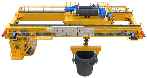
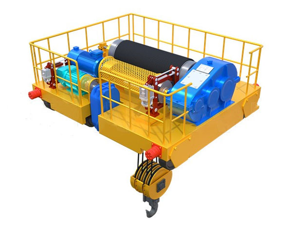
2. Lifting System
- Motor: The power source of the lifting system, usually a three-phase asynchronous motor, provides the required power to lift heavy objects. Depending on the specifications of the crane, the power of the motor will vary.
- Reducer: The motor converts the high motor speed into a lower drum speed through the reducer, while amplifying the torque to ensure that the crane can lift heavier objects. Common types of reducers include worm gear reducers and gear reducers.
- Drum: The wire rope is wound on the drum, and the lifting and lowering of the wire rope is achieved through the rotation of the drum. The diameter and length of the drum are designed according to the lifting height and the length of the wire rope to ensure smooth retraction and release during the lifting process.
- Wire rope: The main load-bearing component for hanging heavy objects. The wire rope needs to have high strength and good flexibility to withstand the tension and wear during the lifting and lowering process.
- Pulley block: The pulley block is used to reduce the tension required during the lifting process and increase the efficiency of the lifting system. The number and arrangement of the pulley block are designed according to the lifting weight, and the pulley and wire rope can be used together to evenly distribute the load.
3. End Carriages
- The end beam usually adopts a box-type structure, which is welded from thick steel plates. The box-type structure can provide high rigidity and bending resistance, ensuring that it is not easy to deform during heavy loads and long-term use. In some small or medium-sized cranes, the end beam may adopt H-shaped steel or I-shaped steel structure. Although this design has a lower manufacturing cost, it may be slightly inferior to the box-type structure in strength and rigidity.
- The end beam is horizontally connected to the two ends of the two main beams, firmly fixing the two main beams together to form a complete bridge structure. The length of the end beam is usually consistent with the span of the crane. The end beam supports the running wheel group of the crane, and the running wheel group transfers the weight of the bridge to the track through the end beam to realize the longitudinal movement of the crane. The running mechanism installed on the end beam is responsible for driving the crane to move smoothly along the track. The end beam evenly distributes the weight transferred from the main beam and the dynamic load of the hoisting trolley to the four support points of the bridge, ensuring the balanced force and stable operation of the entire crane.
- The end beam is usually made of high-strength structural steel to ensure that it can withstand the load from the main beam and the hoisting trolley. Commonly used steel types include Q235B, Q345B, etc. The manufacturing process of the end beam includes steel cutting, welding, machining and surface treatment. Welding quality is a key link in the manufacturing of the end beam, which directly affects the strength and life of the end beam. Machining ensures the precise installation of the walking wheel set and other components.
4. Crane traveling mechanism
- Motor: The crane running mechanism is usually equipped with two or four motors, which drive the walking wheel groups on both sides respectively. The power of the motor is determined according to the size and load requirements of the crane.
- Reducer: Convert the high-speed rotation of the motor into low-speed high-torque output to drive the walking wheel to rotate. Common types of reducers include gear reducers and worm reducers to ensure smooth operation of the crane.
- Drive shaft and coupling: Used to transmit the power output of the reducer to the walking wheel. The coupling connects various mechanical parts, absorbs shock and vibration during operation, and ensures the smoothness of power transmission.
- Driving wheel: Directly driven by the reducer, in contact with the track, to achieve the longitudinal movement of the crane. The number and size of the driving wheels are designed according to the load requirements of the crane.
- Driven wheel: Not directly connected to the motor, it mainly plays a supporting role to maintain the balance of the trolley and good contact with the track.
- Wheel set arrangement: Usually adopt the arrangement of “four-wheel drive and four-slave” or “two-wheel drive and two-slave”, that is, install two sets of driving wheels and two sets of driven wheels on each end beam to ensure the smooth operation of the trolley.
- Electromagnetic brake: When the motor stops working, the electromagnetic brake will automatically apply braking force to prevent the crane from sliding. The design requirements of the brake are to be able to respond quickly to ensure that the trolley operation is stopped in time in an emergency.
- Disc brake: In some large or high-demand cranes, disc brakes may be used to provide stronger braking capacity and higher braking accuracy.
- Busbar system: A system that provides power for the crane operation, usually arranged along the track of the crane. The busbar is connected to the crane’s electrical system by a collector to ensure that the crane is always powered during operation.
- Collector: A component that connects the busbar and the crane’s electrical system to ensure continuous power supply during crane operation. The collector needs to be inspected and maintained regularly to ensure good contact and stable power transmission.
5. Trolley traveling mechanism
- The trolley running mechanism drives the walking wheel group through the motor to drive the trolley to move horizontally along the main beam track. The operator can adjust the moving speed and direction of the trolley through the control system, so as to accurately move the hoisted object to the desired position.
- The speed of the trolley running mechanism can be adjusted according to the operation requirements. The common trolley running speed is between 20m/min and 60m/min. Under certain special working conditions, the frequency converter can also be used to adjust the speed to achieve higher operational flexibility and more precise control.
- The trolley running mechanism is equipped with a travel limit switch. When the trolley moves to the end of the main beam, the limit switch will automatically cut off the power supply of the motor to prevent the trolley from exceeding the track. When multiple trolleys are running on the same main beam, the anti-collision device can prevent collisions between trolleys to ensure safety. When the trolley moves to the end of the main beam, the buffer can absorb the impact force to prevent damage to the trolley structure or track.
- The trolley running mechanism is suitable for various industrial occasions that require horizontal transportation of heavy objects, such as manufacturing workshops, warehouses, port terminals and metallurgical industries. In these occasions, the accuracy and reliability of the trolley’s operation are crucial to improving work efficiency and safety.
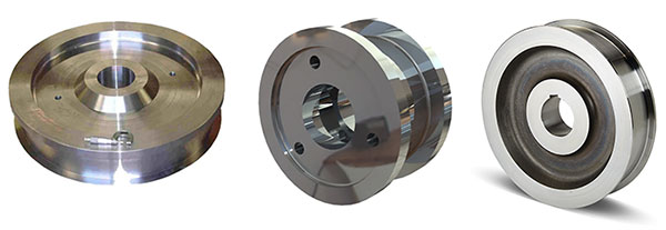
6. Crane wheel
1) Type of wheel:
Driving wheel: responsible for driving the movement of the crane, usually installed at the driving end of the crane, powered by the motor and reducer to make the wheel roll on the track.
Driven wheel: not directly driven by the drive device, mainly plays a supporting and guiding role, usually installed at the non-driving end.
2) Wheel manufacturing process:
Casting process: Casting wheels usually adopt sand casting or precision casting process. Sand casting is suitable for making large wheels, while precision casting is suitable for making wheels with high dimensional accuracy requirements.
Forging process: Forged wheels are formed by high-temperature forging, with higher strength and toughness, suitable for heavy loads and high-frequency use occasions.
Heat treatment: After the wheel is cast or forged, it usually needs to be heat treated (such as quenching and tempering) to improve its hardness and wear resistance.
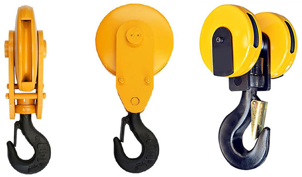
7. Crane hook
- Opening size: The opening size of the hook should be designed to accommodate lifting belts, wire ropes or chains of different diameters, while ensuring that the load does not slip during the lifting process.
- Hook shape: The hook body of the hook is usually designed to be curved to accommodate the center of gravity of the object and ensure uniform force. The curved part should have sufficient strength to withstand tension.
- Rotation mechanism: The hook is usually equipped with a rotation mechanism that allows the hook body to rotate around the vertical axis to avoid entanglement of the wire rope or chain during lifting.
8. Motor
- Hoisting motor: used to drive the lifting mechanism of the crane, responsible for lifting and lowering heavy objects. Usually the power is large and needs to have high torque output capacity.
- Carriage running motor: used to drive the crane’s trolley to move horizontally along the track. Usually two motors drive the wheels on both sides respectively and run synchronously.
- Trolley running motor: used to drive the crane’s trolley to move longitudinally along the main beam. It is small in size but requires precise control.
- Variable frequency motor: Some cranes use variable frequency motors, which adjust the motor speed through the inverter to achieve precise control of the lifting speed and improve the stability of the operation.

9. Sound and light alarm system & limit switch
1) Sound and light alarm system
Warning function: The sound and light alarm system is used to send out sound and light signals during the operation of the crane to alert the operator and surrounding personnel to the operating status of the crane, especially when an abnormal situation occurs or the equipment is about to reach the limit position.
Safety tips: When the crane starts, stops or moves to the preset danger zone, the sound and light alarm system will automatically activate to remind personnel to stay away from the danger zone to avoid collision or other safety accidents.
2) Limit switch
Position limit: The limit switch is used to limit the range of motion of each moving part of the crane to prevent it from exceeding the safe working range. For example, prevent the hook from rising too much and the main beam from moving too much laterally.
Protect equipment: By setting limit switches, mechanical collision, overload or other damage to the equipment during operation can be avoided, and the service life of the equipment can be extended.

10. Safety Devices
- Emergency stop device: In an emergency, the operator can quickly stop all movements of the crane to prevent the accident from expanding. Usually equipped with an emergency stop button, located in the operating table and various easily accessible locations of the crane.
- Electrical protection device: Protect the crane’s electrical system from electrical faults such as overload and short circuit. Automatically cut off power or alarm when an abnormality occurs in the electrical system to ensure the safe operation of the equipment.
- Braking system: Ensure that the load stops safely at the predetermined position during stopping or deceleration. Prevent the hook and load from slipping or reversing when stopping.
- Safety protection device: Prevent the operator or other personnel from being injured during the operation of the equipment. Prevent equipment components from being damaged.
- Automatic lubrication system: Automatically supply oil to key components of the crane (such as bearings and gears) to reduce friction and extend component life. Reduce the frequency of manual lubrication and reduce maintenance workload.
- Overload protection device: Monitor the load weight during crane operation to prevent overload operation and protect the crane and its structural components. When the load exceeds the set safety value, the overload protection device will sound an alarm or automatically stop the crane.
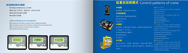
11. Control Mode
- Manual control: Directly control the various motion mechanisms of the crane through a manual operation panel or joystick. The operation method is simple and suitable for working environments that do not require complex control.
- Wireless remote control: Through a wireless remote control, the operator can control the various motion mechanisms of the crane within a certain distance. Suitable for environments that require flexible operation, such as small spaces or working environments that require movement around the crane.
- Automatic control: Automatic control and adjustment of the crane is achieved through a computer system or PLC (programmable logic controller). Suitable for automated production lines or complex working environments that require high precision and high efficiency.
- Semi-automatic control: Combining manual control and automatic control, allowing operators to perform manual operations when necessary, while the system provides automation function support. Suitable for working environments that require both automation functions and human intervention.
- Remote control: Remotely operate the crane through a computer or mobile device, suitable for difficult-to-reach locations or working environments that require centralized control. The operating status of multiple cranes can be centrally monitored to improve management efficiency.
12. Sketch
Application of overhead travelling crane
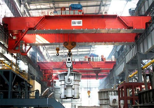
- Heavy manufacturing: Double girder bridge cranes are widely used in heavy industrial fields such as steel and machinery manufacturing to transport heavy materials such as large workpieces, steel plates, and steel structures. In industries such as automobile manufacturing and aircraft manufacturing, double girder bridge cranes are used to transport and install large parts to help achieve efficient production and assembly.
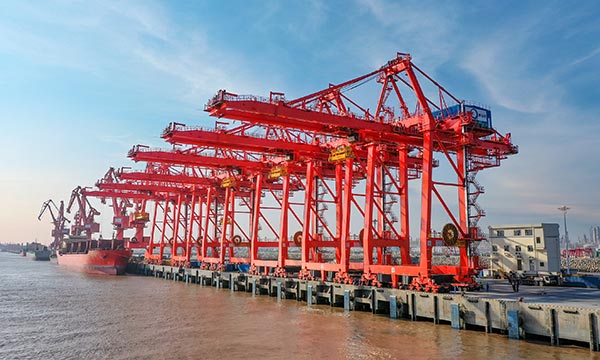
- Ports and docks: Double girder bridge cranes are used to transport and stack containers at ports and docks to support large-scale logistics operations. They are used to load and unload various goods such as bulk cargo, steel, and ore to meet the loading and unloading needs of different types of goods.
- Power industry: In power plants, double girder bridge cranes are used to transport and install large power equipment such as generators and transformers to support the inspection and maintenance of equipment. In hydropower stations, double girder bridge cranes are used to transport heavy equipment such as turbines and generator sets to support the construction and operation of hydropower stations.
- Aerospace: Double girder bridge cranes are used to transport large parts such as aircraft fuselages and wings to help achieve precision manufacturing of aircraft. In the process of spacecraft manufacturing and assembly, double girder bridge cranes are used to transport large parts such as rockets and satellites to support the production and testing of spacecraft.
- Construction Engineering: Double-girder bridge cranes are used to transport and install large components such as bridge trusses, prefabricated parts, etc. in bridge and tunnel construction. They are used to transport construction materials and equipment such as steel bars, concrete components, etc., to support the construction of high-rise buildings.
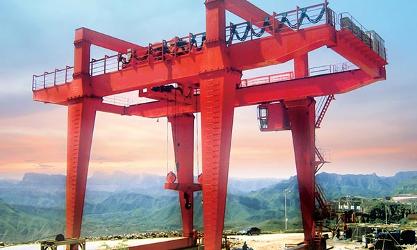
- Mining Industry: In the mining and processing process, double-girder bridge cranes are used to transport ore and mining equipment to support the mining and transportation of ore. They are used to transport and install mining machinery and equipment to support the maintenance and replacement of equipment.
Advantages of overhead travelling crane
Strong flexibility: The specifications, functions and configurations of the crane can be customized according to different working conditions and user needs to meet specific production requirements. The design can be flexibly adjusted to adapt to different plant layouts and production processes.
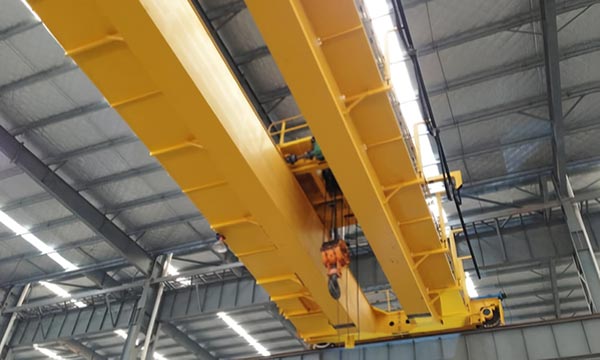
Strong load capacity: Due to the double-beam design, the double-beam bridge crane can carry a larger load and is suitable for heavy and ultra-heavy material handling tasks. The double-beam structure makes the stress distribution of the bridge more uniform, reduces the deformation of the beam, and enhances the stability of the crane.
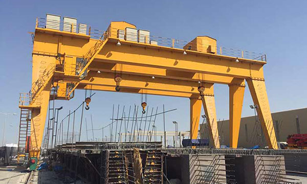
Large span: Double-beam bridge cranes usually have a larger span and can cover a wider working area, which is very suitable for large factories or outdoor operations. Since the hook is installed between the two main beams, it can provide a higher lifting height, which is suitable for scenes requiring high-altitude operations.
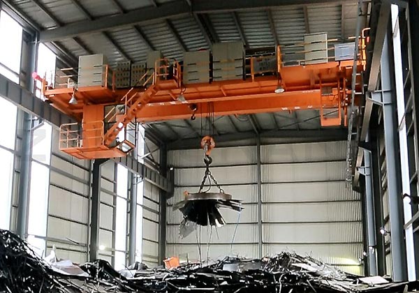
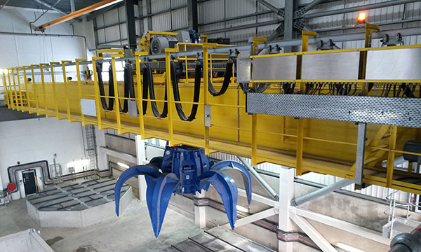
Wide application: Double-beam bridge cranes can be equipped with various types of lifting equipment (such as hooks, grabs, electromagnetic suction cups, etc.) to meet the material handling needs under different working conditions. It is widely used in many industries such as manufacturing, metallurgy, shipbuilding, ports, and electricity. It has strong adaptability and can cope with a variety of complex operating environments.
Complete safety devices: Equipped with overload protection, limit switch, emergency stop button, sound and light alarm system and other safety devices to ensure safe operation. Modern double-beam bridge cranes are usually equipped with automatic control systems to reduce human operating errors and further improve the safety of operations
Main technical data
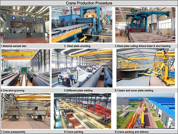
Crane production procedure
Design and planning: Determine the specifications, load, span and other key parameters of the crane according to customer needs and usage environment. Engineers conduct detailed structural design, including the design of components such as double-beam bridge, hoisting trolley, and electrical system. Select appropriate materials according to design requirements, such as steel models and specifications.
Material preparation: Purchase the required steel according to design requirements, such as I-beams, channels, steel plates, etc. Perform quality inspection on steel to ensure that the materials meet design and safety standards.
Manufacturing and processing: Use plasma cutting machines or other cutting equipment to cut steel into the size required by the design drawings. Weld the cut steel to form key components such as double-beam structures and hoisting trolley frames. The strength and quality of the welds must be ensured during welding. Perform mechanical processing on the welded components, such as drilling and grooving, to meet assembly requirements.
Component assembly: Assemble the processed double beams, end beams and other main structural parts. Install the drive unit, winch, motor and other components of the hoisting trolley in place. Install the electrical control system, including cables, switches, control cabinets, etc.
Inspection and debugging: Conduct static load tests in the production workshop to test the structural strength and stability of the crane. Simulate the working state of the crane and test the operating performance of the crane, such as lifting speed, braking effect, etc. Ensure that all safety devices work properly, such as limit switches, emergency stop buttons, etc.
Painting and anti-corrosion: Remove rust and polish the surface of the crane. Apply anti-rust paint and topcoat to improve the anti-corrosion performance and service life of the crane.
Global Market

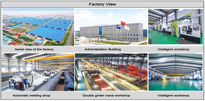
Workshop view
The company has installed an intelligent equipment management platform, and has installed 310 sets (sets) of handling and welding robots. After the completion of the plan, there will be more than 500 sets (sets), and the equipment networking rate will reach 95%. 32 welding lines have been put into use, 50 are planned to be installed, and the automation rate of the entire product line has reached.