

Description
Warning: mysqli_query(): (HY000/1194): Table 'wp_options' is marked as crashed and should be repaired in /www/wwwroot/excelcrane.com/wp-includes/class-wpdb.php on line 2349
Warning: mysqli_query(): (HY000/1194): Table 'wp_options' is marked as crashed and should be repaired in /www/wwwroot/excelcrane.com/wp-includes/class-wpdb.php on line 2349
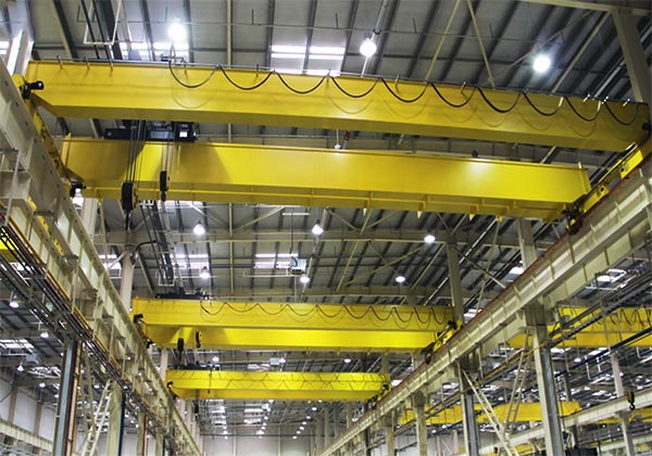
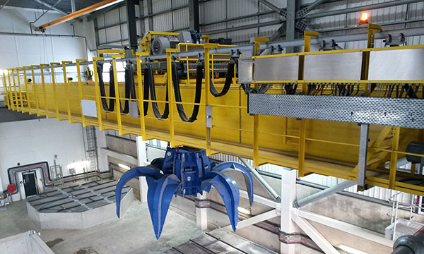
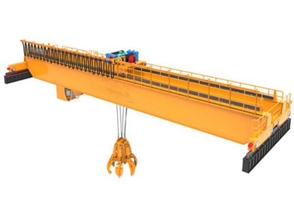
Double-beam bridge grab crane is a heavy lifting equipment, mainly used for grabbing and handling bulk materials such as coal, ore, sand and gravel, grain, etc. It is usually installed in factories, mines, ports, cargo yards and other places, suitable for working environments with efficient loading and unloading and stacking of materials.
The double-beam structure provides stronger bearing capacity and stability, suitable for heavy material handling operations. Its grab can be controlled by electric or hydraulic systems, and can accurately grab, lift and place materials, with simple and efficient operation.
Modern double-beam bridge grab cranes can be configured with automated control systems to reduce manual intervention and improve operating efficiency. It is equipped with a variety of safety protection devices, such as anti-collision systems, overload protection systems and limit devices to ensure safety during operation.
The working process of double-beam bridge grab cranes mainly includes grabbing, lifting, moving and placing materials. The grab is opened and closed by electric or hydraulic drive. After grabbing the material, the lifting device lifts the grab to the set height, and the trolley is driven by the motor to move on the bridge frame to deliver the material to the designated location, and finally place the material.

Components of grab overhead crane
1. Main girder
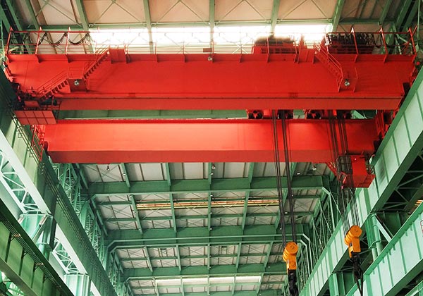
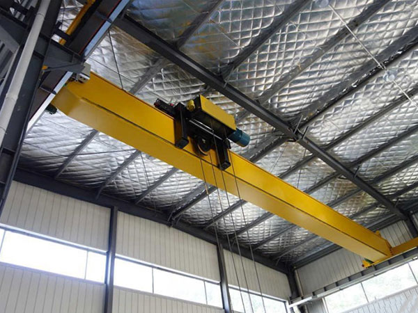
The main beam of a double-beam bridge crane consists of two parallel steel beams, which are usually box-shaped or I-shaped structures. Compared with a single beam, the double-beam design can provide greater load-bearing capacity and higher bending strength, ensuring the stability and safety of the crane when handling heavy objects.
The main beam is usually made of high-quality steel, such as carbon steel or low-alloy high-strength steel. The steel has high strength and good fatigue resistance, and can effectively resist bending and torsional stress. In addition, the steel is treated with anti-corrosion treatment, such as coating or galvanizing, to ensure the durability of the main beam in harsh environments.
The design of the main beam needs to consider factors such as the maximum lifting weight, span, and operating frequency of the crane. Generally, the design standards of the main beam follow national or international crane design specifications, such as ISO standards, GB standards, etc., to ensure the safety and reliability of the structure. The main beam needs to have sufficient rigidity to prevent excessive deformation or bending under heavy load or long-term use. Strength is to resist the action of external forces to ensure that structural failure does not occur under the maximum lifting weight.

2. Lifting System
The lifting system drives the drum to rotate through the lifting motor, and the drum is wound with wire rope, thereby driving the grab bucket to rise. When the material needs to be lifted to a certain height, the motor will drive the drum to rotate at a set speed, and the grab bucket will rise as the wire rope is lifted. After the grab bucket grabs the material, it can be transported to the specified location by the same principle. The lifting process can be controlled manually, or the height can be accurately set by the automation system. When the material is put down, the motor will rotate in the opposite direction, and the drum will release the wire rope, allowing the grab bucket to descend smoothly. The brake quickly stops the rotation of the drum when the grab bucket reaches the set position to ensure the safe placement of the material.
The lifting speed of the double-beam bridge grab crane is usually adjustable, and a variable frequency control system (frequency converter) is used to control the speed of the lifting motor. This allows precise speed adjustment according to different work requirements. For example, when a large amount of material needs to be moved quickly, the lifting speed can be increased; when the material needs to be accurately positioned, the speed can be reduced to ensure accurate material placement.
The lifting system is a key component of the double-beam bridge grab crane, which determines the efficiency, accuracy and safety of the equipment. Through reasonable design and maintenance, the lifting system can provide strong power support for the handling of various heavy materials.

3. End Carriages
The end beam is usually a box-shaped or I-shaped structure, made of high-strength steel, with sufficient strength and rigidity to withstand the load from the main beam and materials. The end beam is generally located at both ends of the crane, parallel to the main beam, forming a solid overall frame.
The design of the end beam needs to consider the span, load capacity and usage scenario of the crane, and must meet national or international crane design specifications. Its main design goal is to ensure the stability, torsion resistance and fatigue resistance of the crane during movement.
The main part of the end beam is usually a closed box-shaped structure, which provides sufficient strength and rigidity to withstand the lateral stress and torque when the crane moves. The lower part of the end beam is equipped with a running wheel, which is responsible for the longitudinal movement of the crane on the track. The running wheel is usually a double-wheel structure, one set of which is the driving wheel driven by the motor; the other set is the driven wheel, which rolls freely as the driving wheel rotates.
A drive motor is usually installed at one end of the end beam to drive the running wheel to realize the movement of the crane on the track. The motor is combined with a reducer to meet the moving speed requirements of the crane. Buffers are usually installed at both ends of the end beam to absorb the impact when the crane reaches its operating limit and avoid damage to the crane structure caused by collision. Some end beam designs will be equipped with guide wheels to ensure that the crane runs smoothly on the track and prevent accidents such as derailment.
4. Crane traveling mechanism
High efficiency: The cart operating mechanism can move quickly on a long track, adapting to large-span operating environments and significantly improving material handling efficiency.
Strong stability: The reasonable design of the traveling wheel set ensures that the cart can run smoothly on the track, reducing shaking and vibration, and improving the accuracy of operations.
High flexibility: The cooperation of the motor and reducer allows the cart to move at different speeds to adapt to different working scenarios and operating needs.
High safety: The design of brakes, limit devices and buffers ensures the safe operation of the cart and avoids safety accidents caused by operating errors or mechanical failures.

5. Trolley traveling mechanism
The trolley running mechanism is mainly composed of the following parts:
- Trolley frame: the main structural component of the trolley, supporting the grab and other equipment on the trolley. The trolley frame is usually a box-type or I-shaped structure to ensure sufficient strength and rigidity.
- Driving device: including motor, reducer and coupling, used to drive the trolley to move on the main beam.
- Travel wheel group: including driving wheel and driven wheel, used to run on the track of the main beam.
- Brake: used to control the start and stop of the trolley to ensure that it can stop safely when needed.
- Limit switch: used to set the movement range of the trolley to prevent the trolley from exceeding the predetermined range.
- Guide wheel: ensure that the trolley runs smoothly on the main beam track to prevent deviation or derailment.
- Buffer device: absorbs impact when the trolley reaches the operating limit to reduce damage to the equipment.
The trolley running mechanism is driven by a motor, and the rotational force of the motor reduces the speed through the reducer and is transmitted to the active travel wheel through the coupling. The rotation of the active travel wheel drives the entire trolley to move on the main beam track. The rotation of the driving wheel cooperates with the driven wheel to ensure that the trolley can move smoothly along the main beam.
During the operation of the trolley, the operator can adjust the moving speed and direction of the trolley through the control system. When the trolley reaches the set operating range, the limit switch will send a signal and the brake will start to ensure that the trolley stops at the specified position.
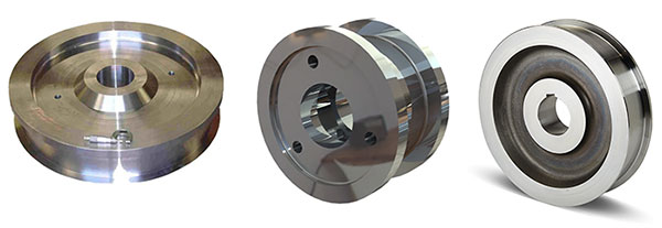
6. Crane wheel
Wheels are prone to wear during long-term use, especially when frequently overloaded and running at high speeds. Therefore, regular inspection and maintenance of wheels is the key to ensuring long-term stable operation of cranes. Common wheel maintenance measures include:
- Regular lubrication: Wheel bearings need to be lubricated regularly to ensure smooth rotation of wheels and reduce friction loss.
- Wear inspection: Regularly check the wear of wheels, especially the rims and wheel surfaces, and polish or replace them if necessary.
- Track inspection: Track wear will accelerate wheel damage, so it is also necessary to regularly check the flatness and wear of the tracks and repair or replace them in a timely manner.
7. Crane hook
The hook is connected to the grab bucket through the lifting system of the crane. When the lifting mechanism is started, the power is transmitted to the hook through the pulley block, driving the grab bucket to perform lifting operations. During operation, the hook needs to withstand the tension and gravity from the heavy object, so its structural design and manufacturing must meet strict strength requirements to ensure the safety of the lifting process.
The load capacity of the hook depends on its size, material and design, and is usually marked with a maximum rated lifting weight. When selecting a hook, it is necessary to select a suitable hook according to the rated lifting weight of the crane and the working requirements of the grab bucket to ensure that it can still work safely under maximum load conditions.
As an important part of the double-beam bridge grab crane, the hook plays a key role in bearing and connection in lifting and grab bucket operations. Its design must not only meet the strength and load requirements, but also must consider safety and ease of operation. Through reasonable material selection, regular inspection and maintenance, and the application of safety devices, the service life of the hook can be effectively extended to ensure the safety and efficiency of crane operations.

8. Motor
Modern double-beam bridge grab cranes usually use a variety of motor control methods to improve the accuracy and automation level of operation:
- Frequency conversion control: The speed of the motor is adjusted by the frequency converter, which can achieve smooth acceleration and deceleration of lifting, running and grab operations to avoid load impact. This method is widely used in lifting motors and running motors.
- PLC control: The action of the motor is programmed and controlled by a programmable logic controller (PLC) to achieve fully automatic or semi-automatic operation, especially in grab opening and closing and material handling. PLC control can improve operating efficiency.
- Remote control: Some modern cranes can operate the motor through a remote control system, allowing the operator to control the operation of the crane from a safe distance.

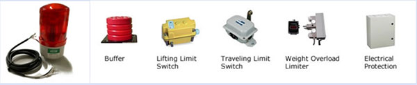
9. Sound and light alarm system & limit switch
1) Sound and light alarm system
- Warning danger: When the crane is abnormal or reaches a dangerous operating state (such as overload or approaching the limit position), the sound and light alarm system will emit obvious sound and light signals to remind the operator to take corresponding measures.
- Ensure safety: The sound and light alarm system can issue an alarm in advance when the equipment is approaching a dangerous state, helping the operator to adjust or stop the operation in time to prevent accidents.
- Indicating equipment status: The system can also be used to display the equipment operation status, such as power on, running, stopped, etc., to help the operator better control the operation of the equipment.
2) Limit switch
- Position limit: The limit switch can detect the limit position of each operating mechanism of the crane, and automatically cut off the power of the motor when approaching these positions to prevent over-travel operation.
- Automatic control: When the grab or lifting mechanism reaches the preset highest or lowest position, the limit switch will automatically interrupt the motor circuit to prevent the equipment from rising or falling too much.
- Safety protection: The limit switch is a protective device to prevent the equipment from entering the dangerous area due to operating errors or system failures, ensuring the safety of personnel and equipment.
10. Safety Devices
Overload limiter: The overload limiter is used to detect the lifting status of the crane and prevent the equipment from continuing to operate when it exceeds the rated load, avoiding equipment damage or safety hazards caused by overload. Prevent the crane from being damaged due to overload and extend the service life of the equipment. Ensure the safety of operators and prevent accidents caused by uncontrolled lifting.
Emergency stop button: The emergency stop button is a manual control device that allows the operator to quickly stop all actions of the crane in any dangerous situation to prevent accidents.
Anti-collision device: The anti-collision device is used to avoid collision accidents between the crane’s trolley, car or grab during operation. Prevent collisions between two cranes or various parts of the crane to reduce the possibility of equipment damage and safety accidents.
Windproof device: The windproof device is used in outdoor working environments to prevent the crane from moving or overturning due to wind when the wind reaches a certain level. It is particularly suitable for double-beam bridge grab cranes operating in ports and open fields. Ensure the stability of the equipment under strong wind conditions, prevent the crane from accidentally moving or overturning due to strong winds, and reduce the risk of property loss and casualties.
Braking system: The braking system is a device that ensures that all moving parts can be stopped promptly and reliably during the operation of the crane. It is mainly used for the lifting mechanism, trolley running mechanism and car running mechanism.
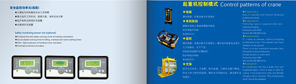
11. Control Mode
Manual control: Manual control is the most basic and traditional form of control. It is usually controlled by the operator directly using the operation panel or joystick to control the various actions of the crane. The operation is simple and intuitive, which makes it easy for the operator to adjust the operation according to the actual situation. The equipment cost is relatively low and the maintenance is simple.
Remote control: Remote control is to remotely operate the crane through a wireless or wired remote control device, which is suitable for use in scenarios where there are safety risks or long-distance control is required. The operator can control it in a safe area away from the equipment, which is suitable for dangerous working environments. It improves operational flexibility and can monitor and operate the crane in different locations.
Centralized control room control: Centralized control room control refers to the operator centrally managing and operating the crane through a computer system or operating console in the centralized control room. This method is often used in large industrial sites or ports where multiple cranes need to work together. It is suitable for centralized control and management of multiple equipment, which improves overall production efficiency. The operator does not need to work directly on site, which reduces on-site safety risks.
12. Sketch

Advantages of grab overhead crane
Strong carrying capacity: The double-beam structure design enables the crane to have a high carrying capacity, capable of handling heavy materials, and suitable for heavy industrial operations.
Wide working range: The bridge design enables it to cover a large working area, making it convenient to move and lift materials throughout the work site.
High operating stability: The double-beam design makes the crane structure more stable, with less vibration during operation and smoother grab operation.
Efficient material grabbing: The crane equipped with a grab can quickly grab, load and unload bulk materials such as coal, sand, gravel, ore, etc., with high efficiency, suitable for large-scale loading and unloading operations.
High degree of automation: It can be equipped with an automated control system to achieve precise control and remote operation, reduce manual intervention, and improve work efficiency.
Low maintenance cost: The double-beam bridge crane has a relatively simple structure, relatively convenient daily maintenance, long service life, and reduces long-term operating costs.
Strong adaptability: The crane can customize the grab type (such as hydraulic grab, mechanical grab, etc.) according to different working scenarios, and flexibly respond to different material handling needs.

Application of grab overhead crane
Double-beam bridge grab cranes are widely used in the following occasions due to their strong carrying capacity and efficient material grabbing performance:
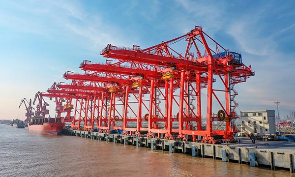
Ports and docks: used for bulk cargo loading and unloading, such as coal, ore, sand and gravel, grain and other materials. In ports, docks and other places, it can load and unload bulk cargo in large quantities and efficiently.
Power plants: used for the transportation and loading and unloading of raw materials such as coal and ore. Power plants require a large amount of coal to maintain power generation, and double-beam bridge grab cranes can quickly handle the handling of these materials.
Mining and metallurgical industries: During the transportation and storage of bulk materials such as ore, sand and gravel, the equipment can effectively perform stacking and loading and unloading operations.
Steel mills: used to handle bulk materials such as iron ore, steel slag, scrap steel, etc., to improve production efficiency and reduce labor costs.
Cement plants: During the transportation and stacking of materials such as cement, limestone, clinker, etc., double-beam bridge grab cranes can quickly complete the loading and unloading and handling of materials.
Waste treatment plant: used to treat domestic waste, industrial waste, etc. in waste incineration plants. Grab buckets can help quickly grab, load and transport waste to designated locations.
Construction sites: used to transport construction materials, especially some bulk materials such as sand and stone.
Warehousing and logistics: In the field of bulk warehousing, double-beam bridge grab cranes can help efficiently complete the stacking and transfer of materials.

Main technical data

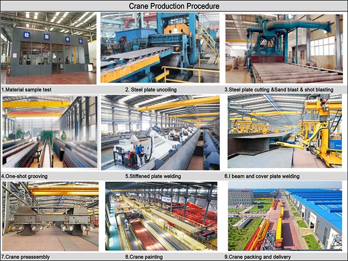
Crane production procedure
1. Demand analysis and design stage: Demand analysis is conducted based on the customer’s actual usage needs, working environment, lifting capacity, grab type, etc. Design engineers determine the specifications of the crane, grab form (such as mechanical or hydraulic), working parameters, etc. according to the needs, and draw a preliminary design plan. Conduct a technical review of the design plan to ensure that all parameters meet safety standards and perform structural optimization.
2. Material procurement: According to the specifications of the design drawings, purchase high-strength steel, grab parts, motors, reducers, brakes and other major accessories. According to the requirements of crane automation, purchase corresponding control systems, sensors, inverters and other electrical equipment.
3. Structural parts manufacturing: The purchased steel is cut using a CNC cutting machine according to the requirements of the design drawings and formed into key structural components such as double beams, main beams, and end beams. The cut steel is welded to form the main structure of the crane (double beams, bridges, etc.), and the welding needs to ensure strength and durability. The metal structure after welding is surface treated, such as rust removal, sandblasting, etc., and coated with anti-corrosion paint to extend the service life of the crane.
4. Grab bucket production: According to different types of grab buckets, make the grab bucket’s key components such as claws, hinges, hydraulic cylinders, etc. Assemble the various components of the grab bucket and install the hydraulic or mechanical transmission system according to the work requirements.
5. Machining and assembly: Process the key mechanical components of the crane, such as wheels, bearings, reducers, etc., to ensure that the accuracy of each component meets the design requirements. Assemble the double beam, bridge frame, grab bucket and other structures to ensure the matching and installation accuracy between the components. Install the motor, reducer, winch system, grab bucket lifting system, etc.
6. Electrical system installation: Install the crane’s electrical control system according to the design drawings, including frequency converters, switches, sensors, remote control systems, etc. Cable wiring is performed on various parts of the crane to ensure that various parts of the electrical system can operate smoothly. If it is an automated crane, the control software needs to be installed, and the program needs to be debugged and optimized.
7. Testing and debugging: The assembled crane is tested for no-load and full-load operation to ensure its load-bearing capacity, operating speed and grab bucket grabbing accuracy. Check the operation of the electrical system to ensure that the control system can work properly. Check the crane’s brake system, limiters, safety devices, etc. to ensure compliance with relevant safety standards.
8. Installation and on-site commissioning: Assemble the crane components transported to the customer’s site on-site to ensure that each part is correctly installed according to the drawing requirements. After the installation is completed, conduct the final load test and grab operation commissioning to ensure that the crane can operate normally in the actual working environment.
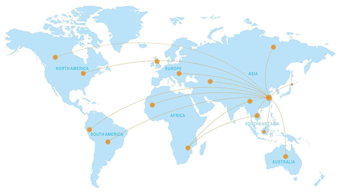
Global Market
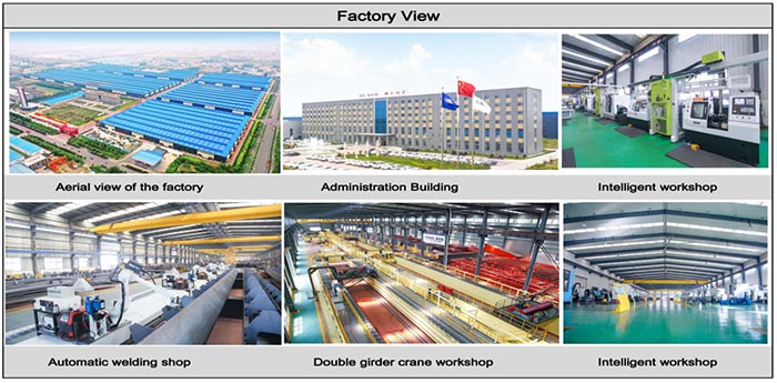
Workshop view
The company has installed an intelligent equipment management platform, and has installed 310 sets (sets) of handling and welding robots. After the completion of the plan, there will be more than 500 sets (sets), and the equipment networking rate will reach 95%. 32 welding lines have been put into use, 50 are planned to be installed, and the automation rate of the entire product line has reached.